 IEEE/ICACT20250085 Slide.07
[Big Slide]
Oral Presentation
| Virual Oral Presentation Slide by Slide |
|
IEEE/ICACT20250085 Slide.07
[Big Slide]
| Oral Presentation |
|
|
|
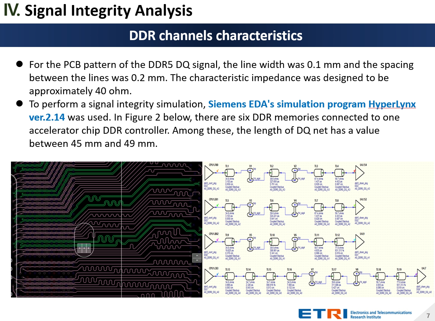
For the PCB pattern of the DDR5 DQ signal, the line width was 0.1 mm and the spacing between the lines was 0.2 mm. The characteristic impedance was designed to be approximately 40 ohm. To perform a signal integrity simulation, Siemens EDA's simulation program HyperLynx ver.2.14 was used. In Figure 2 below, there are six DDR memories connected to one accelerator chip DDR controller. Among these, the length of DQ net has a value between 45 mm and 49 mm. | |
| [Go to Next Slide] |