 |
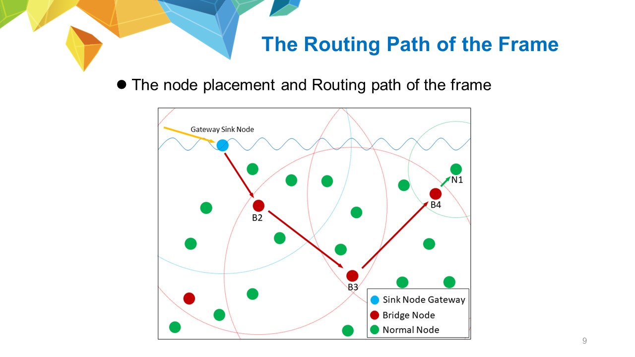
The figure show the system operates when a frame is transmitted from external network to N1. First, the frame enters the sink node gateway from an external network and the frame is translated into the format for underwater communication. The sink node gateway is its starting point in underwater network. When the frame is transmitted to B2, its group number is changed to 2. Because the group number of the sink node gateway and green normal nodes near B2 is 3, they stop receiving the frame and go in idle status, instead of wasting power in analyzing the frame. If a routing protocol can build a routing table for all bridge nodes and the sink node gateway, including the information of all network nodes, the bridge nodes B2, B3 and B4 in group 2 all have the detailed routing table of the underwater network and the routing table can bind normal nodes and bridge nodes together. When receiving frames from other bridge nodes, each bridge node can search for the destination address to modify the next-hop node MAC address of the header.
|
 IEEE/ICACT20240381 Slide.08
[Big Slide]