 |
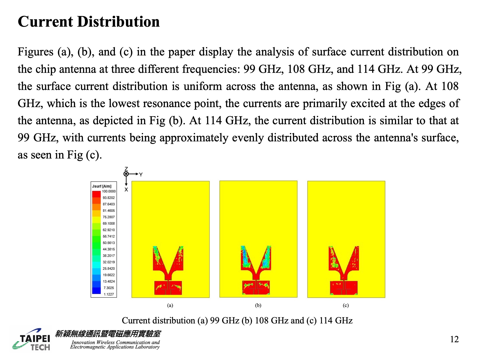
In the paper, Figures (a), (b), and (c) illustrate the surface current distribution on the chip antenna at three distinct frequencies: 99 GHz, 108 GHz, and 114 GHz. Figure (a) shows that at 99 GHz, the current distribution is even across the antenna. Figure (b) depicts the situation at 108 GHz, the antenna's lowest resonance point, where the currents are mainly concentrated at the antenna's edges. Finally, Figure (c) demonstrates that at 114 GHz, the current distribution resembles that at 99 GHz, with the currents being fairly uniformly distributed over the antenna's surface. |
 IEEE/ICACT20240052 Slide.12
[Big Slide]