 IEEE/ICACT20220074 Slide.15
[Big Slide]
Oral Presentation
| Virual Oral Presentation Slide by Slide |
|
IEEE/ICACT20220074 Slide.15
[Big Slide]
| Oral Presentation |
|
|
|
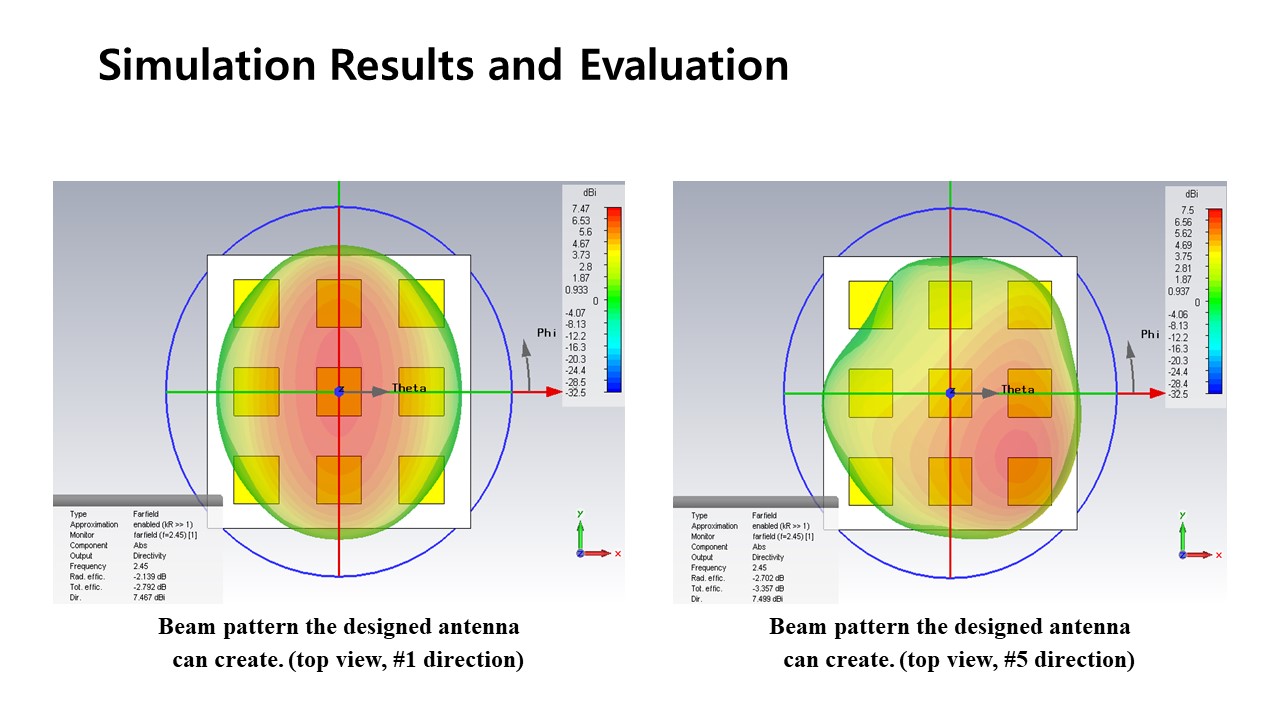
These figures show example beam patterns of the 3x3 ESPAR antenna. These are captured from the top. The left-side figure shows the beam pattern when a reactance set for direction #0 is applied to the antenna. and the maximum beam gain is about 7.47 dBi. The right-side figure shows the beam pattern when a reactance set for direction #5 is applied to the antenna and the maximum beam gain is about 7.5 dBi. The beam patterns are well formed in the target direction according to the reactance set. | |
| [Go to Next Slide] |