 ICACT20240055 Slide.20
[Big slide for presentation] |
Chrome Text-to-Speach Click!! |
 |
• Thank you for listening
|
|
ICACT20240055 Slide.19
[Big slide for presentation]
|
Chrome Text-to-Speach Click!! |
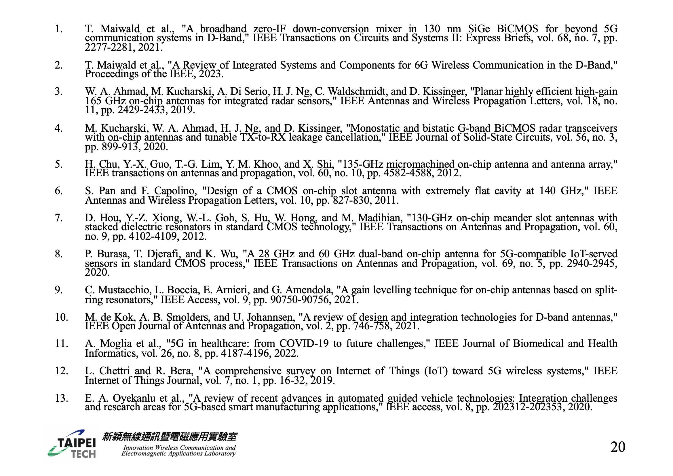 |
• This is our reference
|
|
ICACT20240055 Slide.18
[Big slide for presentation]
|
Chrome Text-to-Speach Click!! |
 |
REFERENCES
|
|
ICACT20240055 Slide.17
[Big slide for presentation]
|
Chrome Text-to-Speach Click!! |
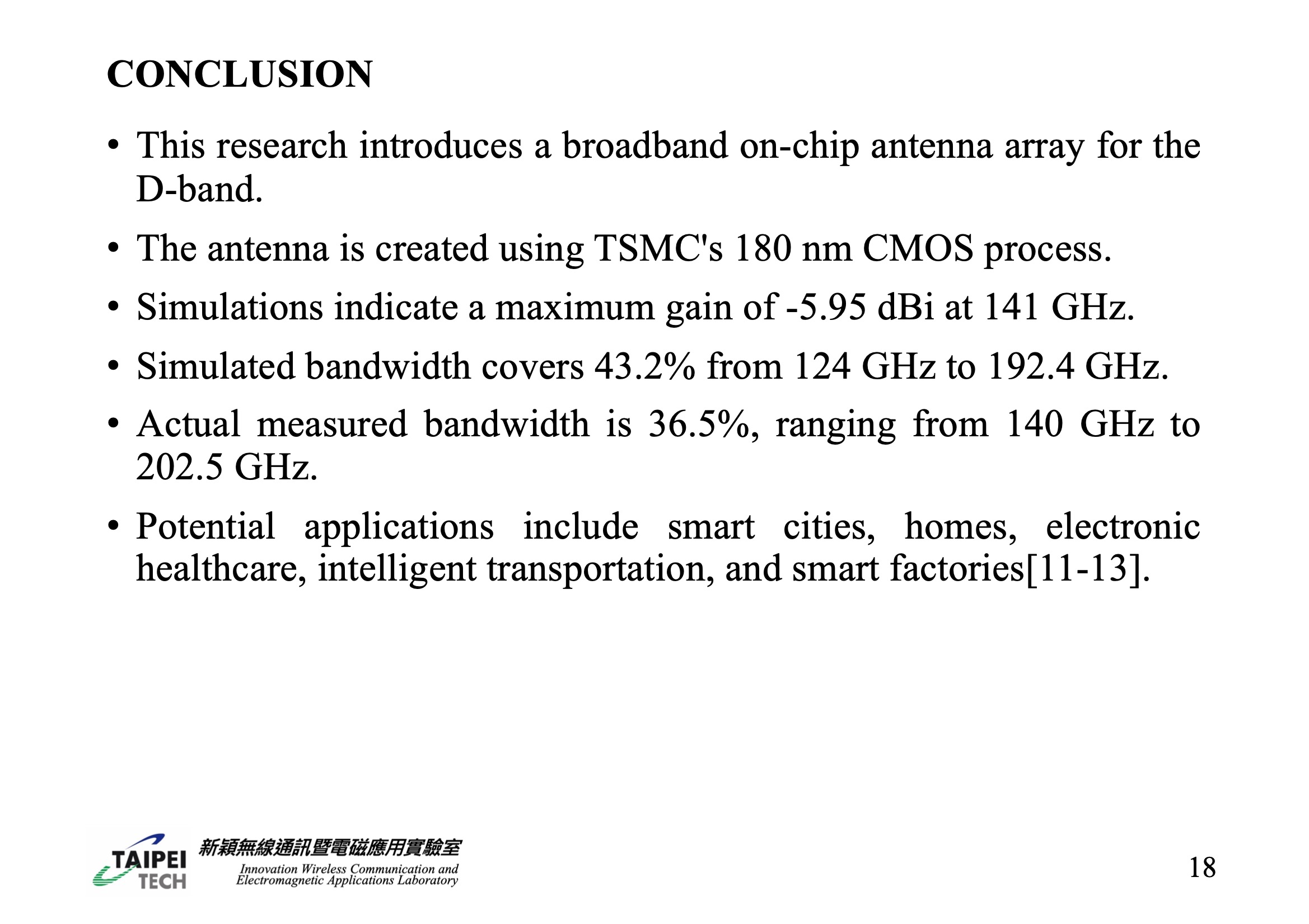 |
• - In this research, we introduced a broadband on-chip antenna array designed to operate in the D-band. This antenna was developed using TSMC's 180 nm CMOS process. The simulation results indicate that at 141 GHz, the antenna achieves a maximum gain of -5.95 dBi and has a simulated bandwidth percentage of 43.2%, covering frequencies from 124 GHz to 192.4 GHz. In practical measurements, the bandwidth was found to be 36.5%, spanning from 140 GHz to 202.5 GHz. This antenna has potential applications in various fields, including Smart cities, smart homes, electronic healthcare, intelligent transportation systems, and smart factories, as referenced in studies 11 to 13.
|
|
ICACT20240055 Slide.16
[Big slide for presentation]
|
Chrome Text-to-Speach Click!! |
 |
CONCLUSION
|
|
ICACT20240055 Slide.15
[Big slide for presentation]
|
Chrome Text-to-Speach Click!! |
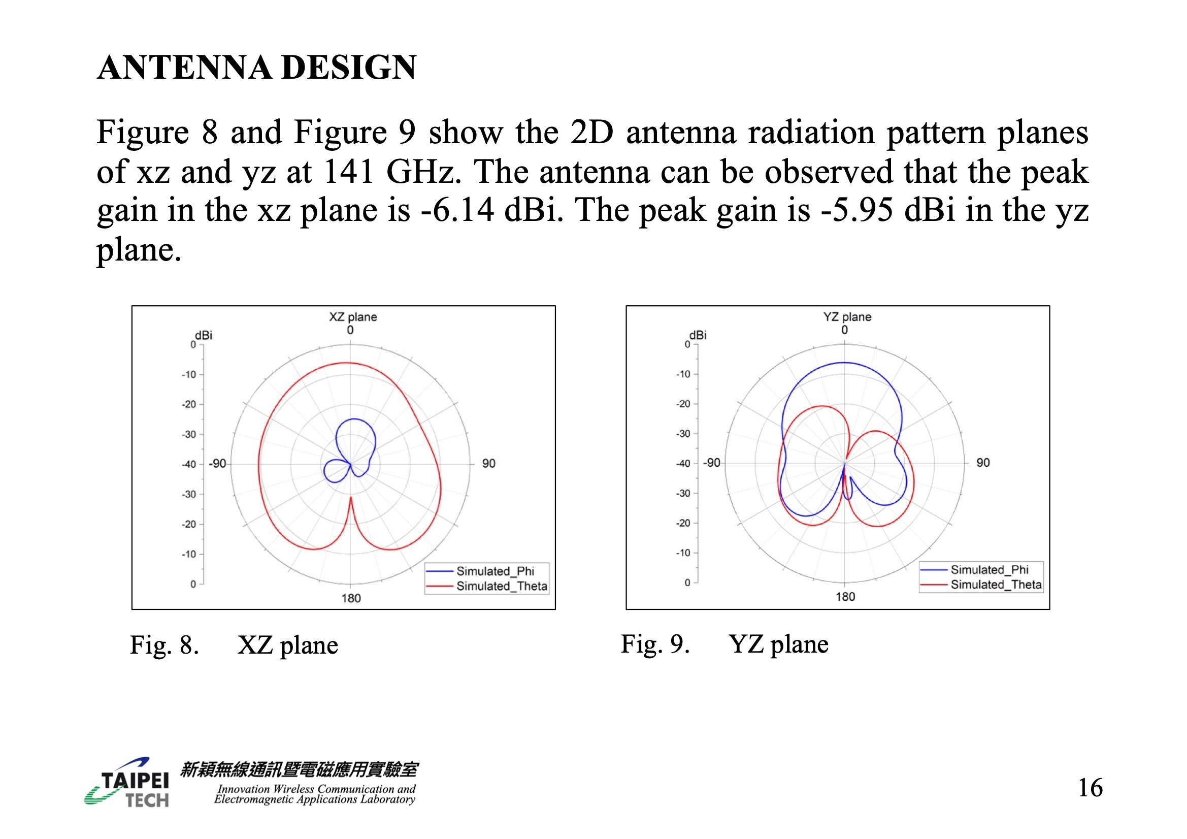 |
• - Figures 8 and 9 display the two-dimensional radiation patterns of the antenna in the xz and yz planes, respectively, at 141 GHz. In these figures, it's noted that the peak gain of the antenna in the xz plane is -6.14 dBi, while in the yz plane, the peak gain is slightly higher at -5.95 dBi.
|
|
ICACT20240055 Slide.14
[Big slide for presentation]
|
Chrome Text-to-Speach Click!! |
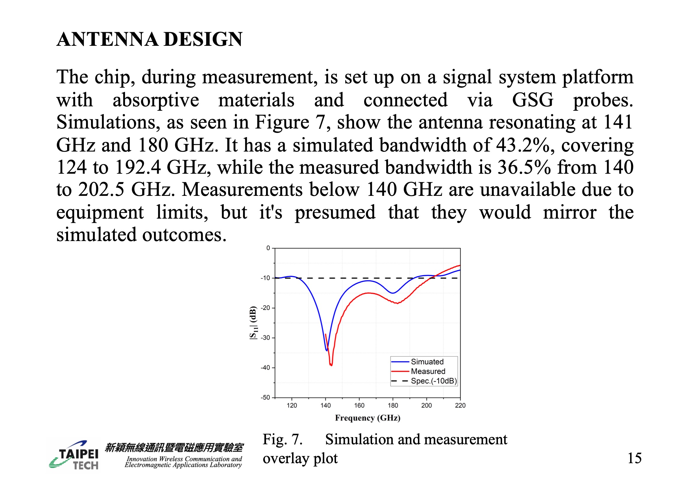 |
• - For the measurement process, the chip antenna was placed on a platform within the signal source system, surrounded by absorbing material, and connected via GSG probes. As shown in Figure 7, the simulation results reveal that the chip antenna resonates at two frequencies, 141 GHz and 180 GHz. The simulated bandwidth of the antenna is 43.2%, covering a frequency range from 124 GHz to 192.4 GHz. In contrast, the measured bandwidth is slightly narrower at 36.5%, spanning from 140 GHz to 202.5 GHz. Due to the limitations of the measuring instrument, which can only assess frequencies between 140 and 220 GHz, it wasn't possible to obtain measurement results below 140 GHz. However, extrapolating from the measurement trends observed between 140 and 220 GHz, it's inferred that the performance below 140 GHz would likely align with the simulation results.
|
|
ICACT20240055 Slide.13
[Big slide for presentation]
|
Chrome Text-to-Speach Click!! |
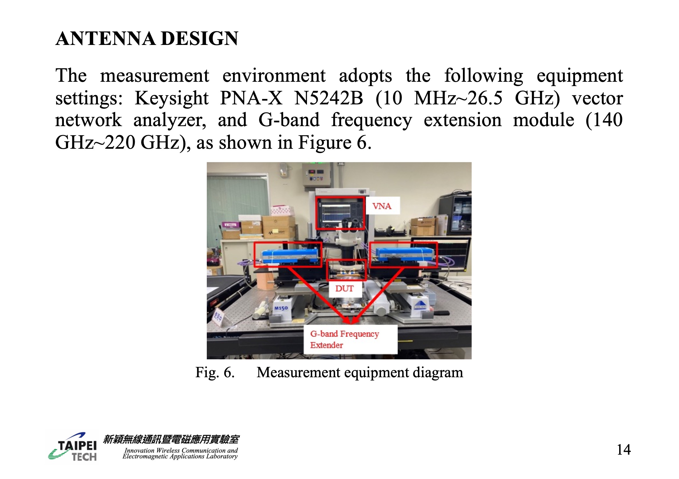 |
• - The setup for measuring the antenna involved specific equipment: a Keysight PNA-X N5242B vector network analyzer, which operates in the range of 10 MHz to 26.5 GHz, and a G-band frequency extension module that covers frequencies from 140 GHz to 220 GHz. This measurement setup is depicted in Figure 6.
|
|
ICACT20240055 Slide.12
[Big slide for presentation]
|
Chrome Text-to-Speach Click!! |
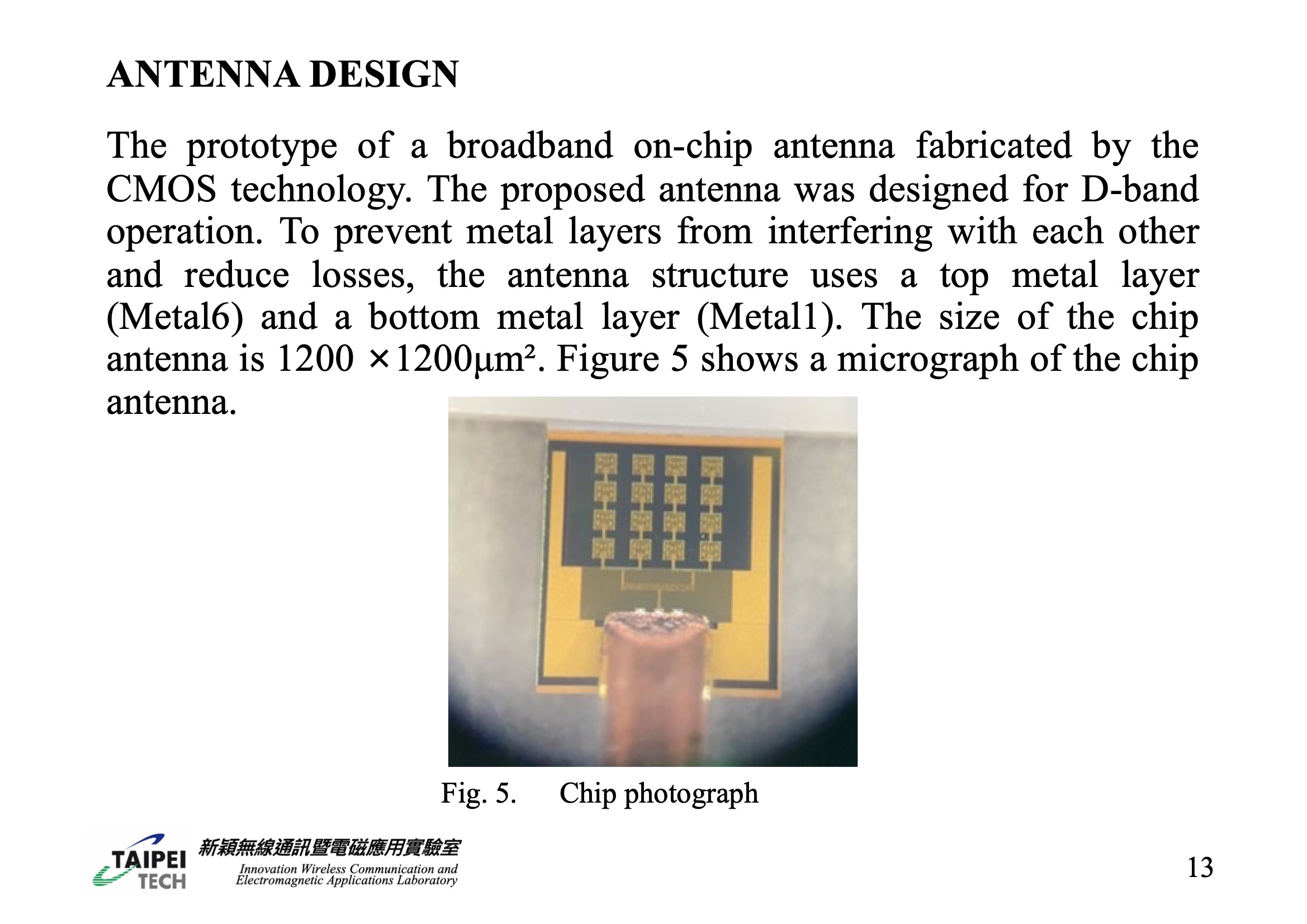 |
• - A prototype of a broadband on-chip antenna has been fabricated using CMOS technology, specifically designed for D-band frequencies. In order to minimize interference between metal layers and reduce losses, the antenna's design incorporates a top metal layer (Metal6) and a bottom metal layer (Metal1). The dimensions of this chip antenna are 1200 × 1200 μm². A micrograph of this chip antenna is displayed in Figure 5.
|
|
ICACT20240055 Slide.11
[Big slide for presentation]
|
Chrome Text-to-Speach Click!! |
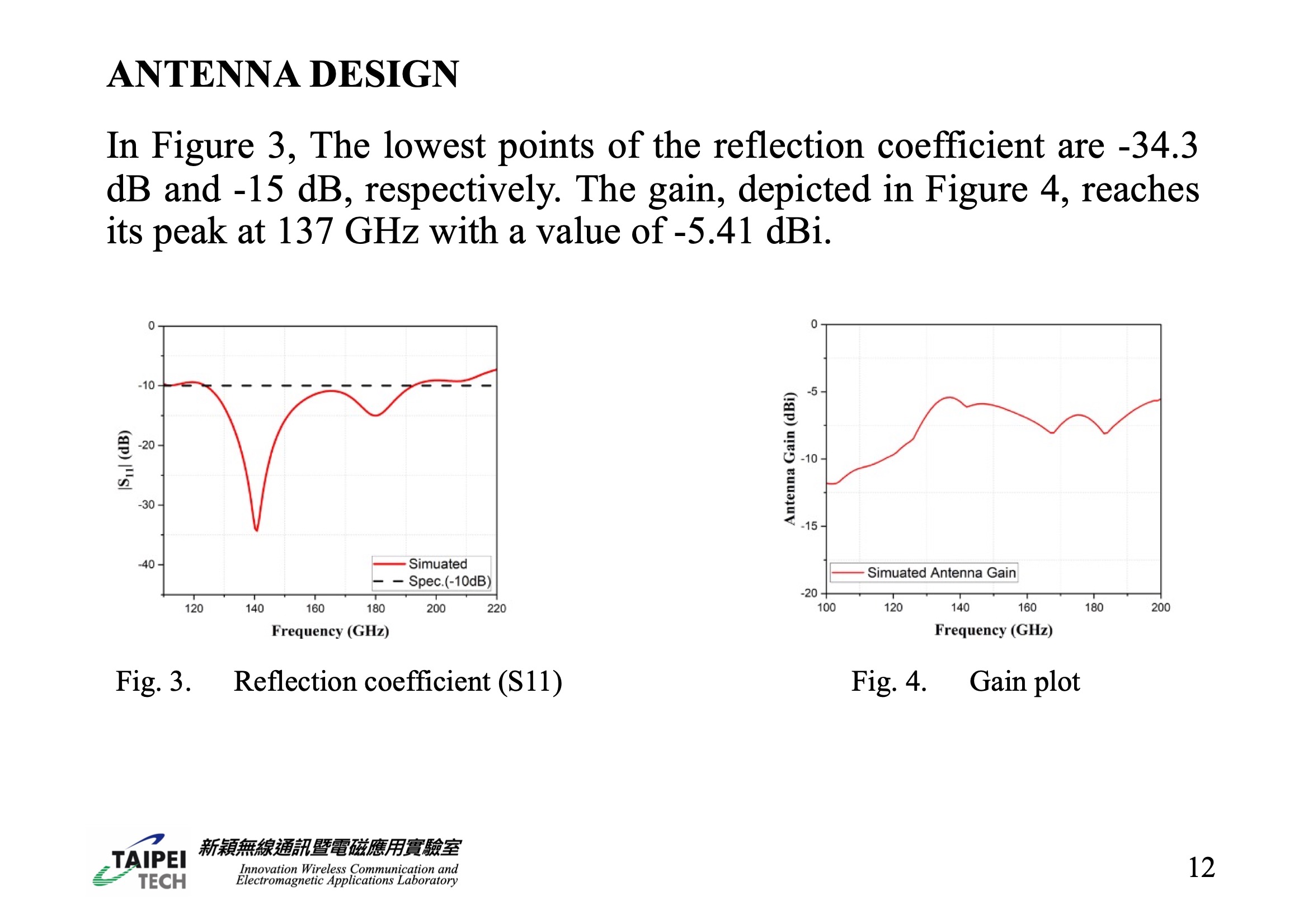 |
• - Figure 3 shows that the reflection coefficient of the antenna has its lowest points at -34.3 dB and -15 dB. Furthermore, as illustrated in Figure 4, the antenna's gain peaks at 137 GHz, achieving a value of -5.41 dBi.
|
|
ICACT20240055 Slide.10
[Big slide for presentation]
|
Chrome Text-to-Speach Click!! |
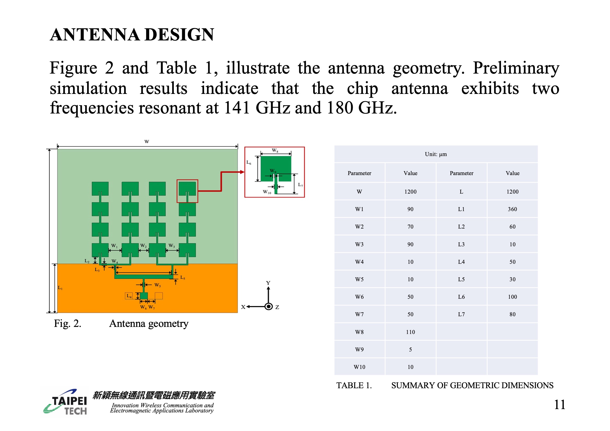 |
• - Figure 2 and Table 1 in the paper provide a detailed illustration of the antenna's geometry. Initial simulations suggest that this chip antenna demonstrates resonance at two distinct frequencies, specifically at 141 GHz and 180 GHz.
|
|
ICACT20240055 Slide.09
[Big slide for presentation]
|
Chrome Text-to-Speach Click!! |
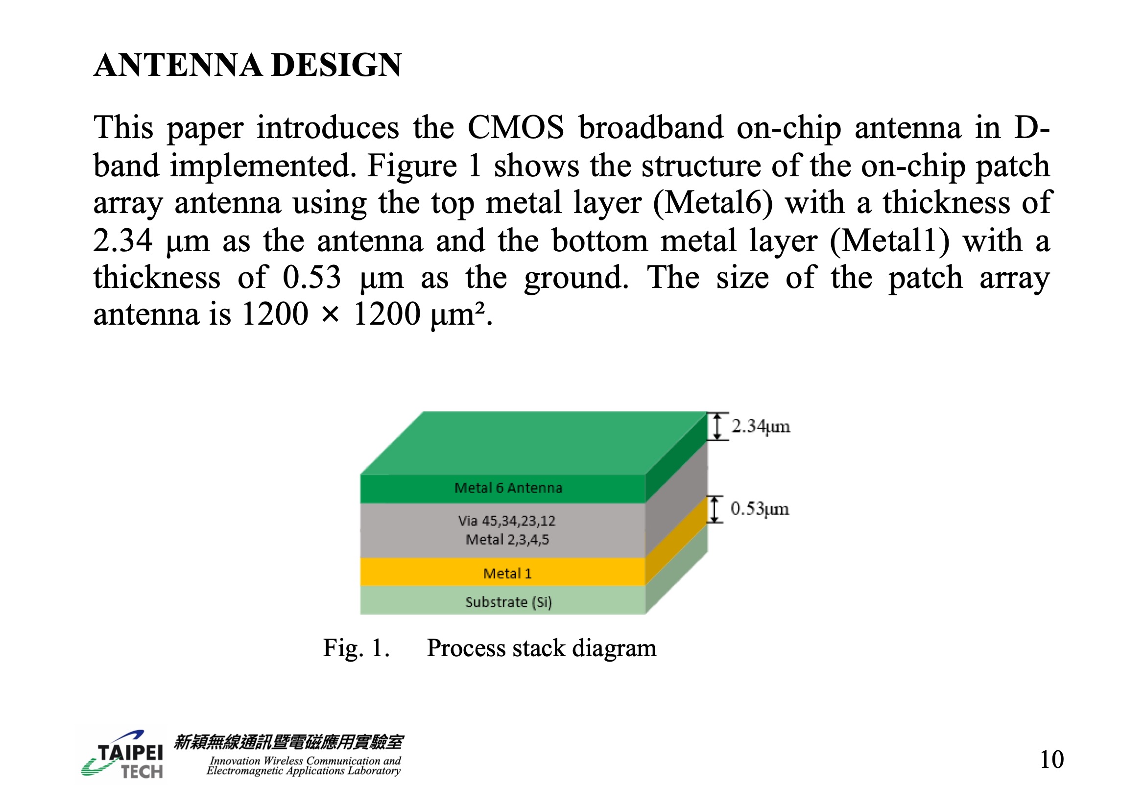 |
• - This study presents the implementation of a CMOS broadband on-chip antenna for D-band applications. As depicted in Figure 1, the antenna's structure consists of an on-chip patch array. This array utilizes the top metal layer, Metal6, which is 2.34 μm thick, to serve as the antenna. The bottom metal layer, Metal1, with a thickness of 0.53 μm, acts as the ground. The overall dimensions of this patch array antenna are 1200 × 1200 μm².
|
|
ICACT20240055 Slide.08
[Big slide for presentation]
|
Chrome Text-to-Speach Click!! |
 |
ANTENNA DESIGN
|
|
ICACT20240055 Slide.07
[Big slide for presentation]
|
Chrome Text-to-Speach Click!! |
 |
• - In this study, we introduce a broadband on-chip array antenna designed for the D-band frequency range. This antenna has been developed using CMOS technology. Our simulation results show that this antenna achieves a peak gain of -5.95 dBi at 141 GHz. Additionally, its operational bandwidth, measured by the -10 dB standard, extends from 140 GHz to 202.5 GHz. The versatility of this antenna design makes it suitable for various applications, including in the industrial, healthcare, and automotive sectors [10].
|
|
ICACT20240055 Slide.06
[Big slide for presentation]
|
Chrome Text-to-Speach Click!! |
 |
• - The dual-frequency helical monopole chip antenna, which combines a helical structure with a package substrate, alongside a linear monopole antenna, enhances the radiation efficiency and achieves a dual-frequency band operation. This antenna configuration yields an efficiency of 45% at 28 GHz and 30% at 60 GHz [8]. Additionally, a square ring resonator (SRR) is employed to counteract the issue of gain reduction. Through experimentation, it was found that a gain decrease of around 7 dBi at 85 GHz can be effectively compensated, and at 81.5 GHz, a maximum gain improvement of 1.61 dBi is achievable [9]. These results underscore the effectiveness of these designs in mitigating gain losses at specific frequencies.
|
|
ICACT20240055 Slide.05
[Big slide for presentation]
|
Chrome Text-to-Speach Click!! |
 |
• - In recent times, there has been significant research in the field of mmWave chip antennas. One study, referenced as [5], explored the use of a patch antenna array alongside a planar monopole antenna, which featured multiple membrane supports and a polymer cavity. Under this setup, the patch array antenna achieved a maximum gain of 8.66 dBi and a bandwidth ranging from 126.5 to 138 GHz at 130 GHz. Another approach to enhance the performance of slot antennas involves introducing a cavity, which has been shown to increase the gain to -2 dBi [6]. Furthermore, incorporating a stacked dielectric resonator (DR) into a 130 GHz meandering slot antenna has demonstrated improvements in both efficiency and gain, with experimental results showing a 43% radiation efficiency and a gain of 4.7 dBi at 130 GHz [7].
|
|
ICACT20240055 Slide.04
[Big slide for presentation]
|
Chrome Text-to-Speach Click!! |
 |
The D-band's frequency band is characterized by shorter wavelengths, allowing for the integration of antennas onto chips at a more affordable cost. However, this often results in lower antenna gains, potentially leading to weaker signal reception. To counteract this issue and ensure effective communication, it becomes essential to boost the transmit power of these chip antennas, thereby mitigating any adverse effects on the system's performance.
|
|
ICACT20240055 Slide.03
[Big slide for presentation]
|
Chrome Text-to-Speach Click!! |
 |
The 5G mmWave frequency band, encompassing frequencies like 28 GHz and 40 GHz, has ushered in an era of higher data transmission needs. These bands, with a sub-span of 800 MHz, can achieve transmission speeds of up to 10 Gbit/s. However, as the thirst for faster data speeds grows, there's a pressing need for even higher transmission rates and broader bandwidths. This is where the D-band, ranging from 110 to 170 GHz and offering frequencies above 100 GHz, becomes crucial. It provides a significantly aggregated bandwidth, which is capable of supporting transmission rates as high as 100 Gbit/s.
|
|
ICACT20240055 Slide.02
[Big slide for presentation]
|
Chrome Text-to-Speach Click!! |
 |
INTRODUCTION
|
|
ICACT20240055 Slide.01
[Big slide for presentation]
|
Chrome Text-to-Speach Click!! |
 |
• - In this presentation, we will cover the following sections:
• - Introduction
• - Antenna design
• - Conclusion
• - References
|
|
ICACT20240055 Slide.00
[Big slide for presentation]
[YouTube] |
Chrome Text-to-Speach Click!! |
 |
Today's presentation, delivered by myself, Shang-Jui Huang, highlights the design of a Broadband On-Chip antenna array in CMOS technology for D-band applications, a collaborative effort also authored by Ming-An Chung and Yu-Hsun Chen.
|
















