 ICACT20240287 Slide.20
[Big slide for presentation] |
Chrome Text-to-Speach Click!! |
 |
Thank you very much for your time, I am willing to answer any questions that you might have.
|
|
ICACT20240287 Slide.19
[Big slide for presentation]
|
Chrome Text-to-Speach Click!! |
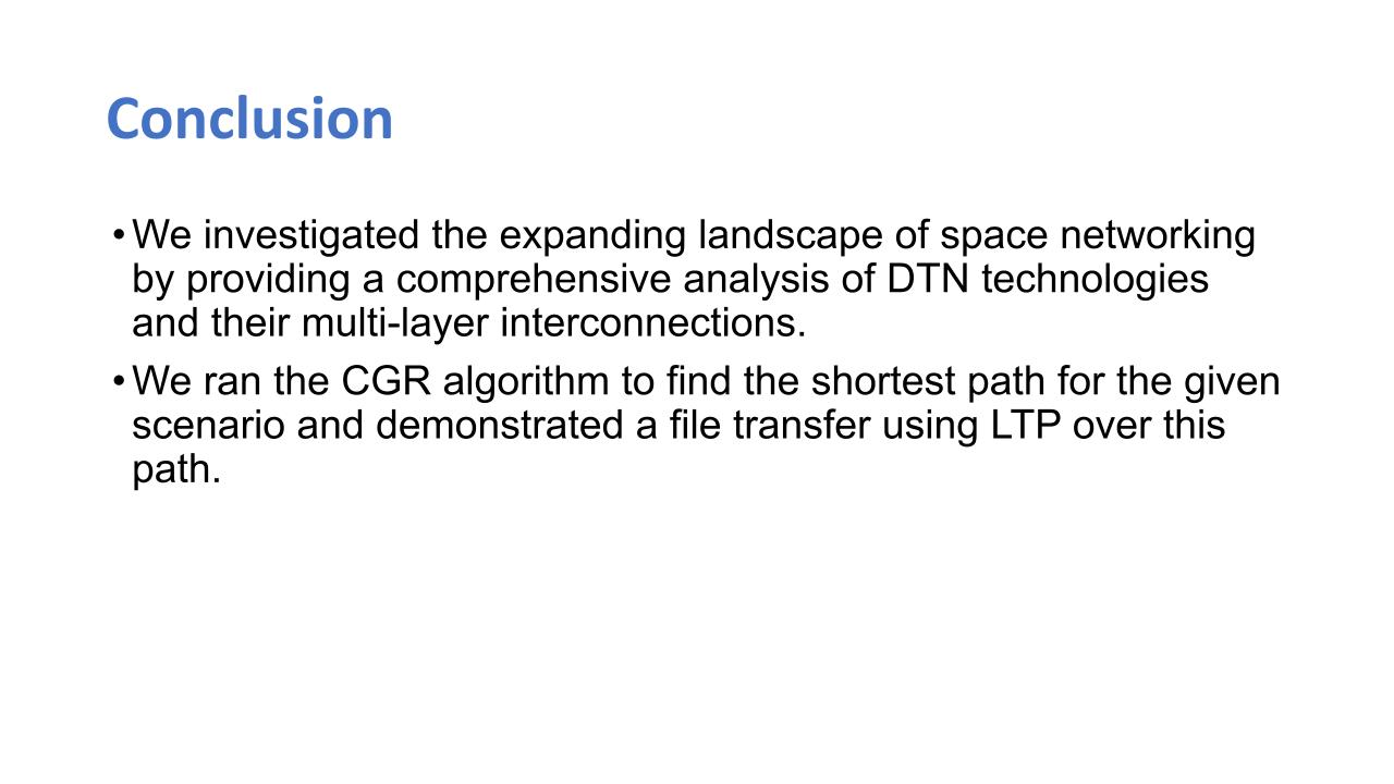 |
In conclusion, we investigated the expanding landscape of space networking by providing a comprehensive analysis of the DTN technology and their multi-layer interconnections. We also ran the CGR algorithm to find the shortest path for the given scenario and demonstrated a file transfer using the LTP over this path.
|
|
ICACT20240287 Slide.18
[Big slide for presentation]
|
Chrome Text-to-Speach Click!! |
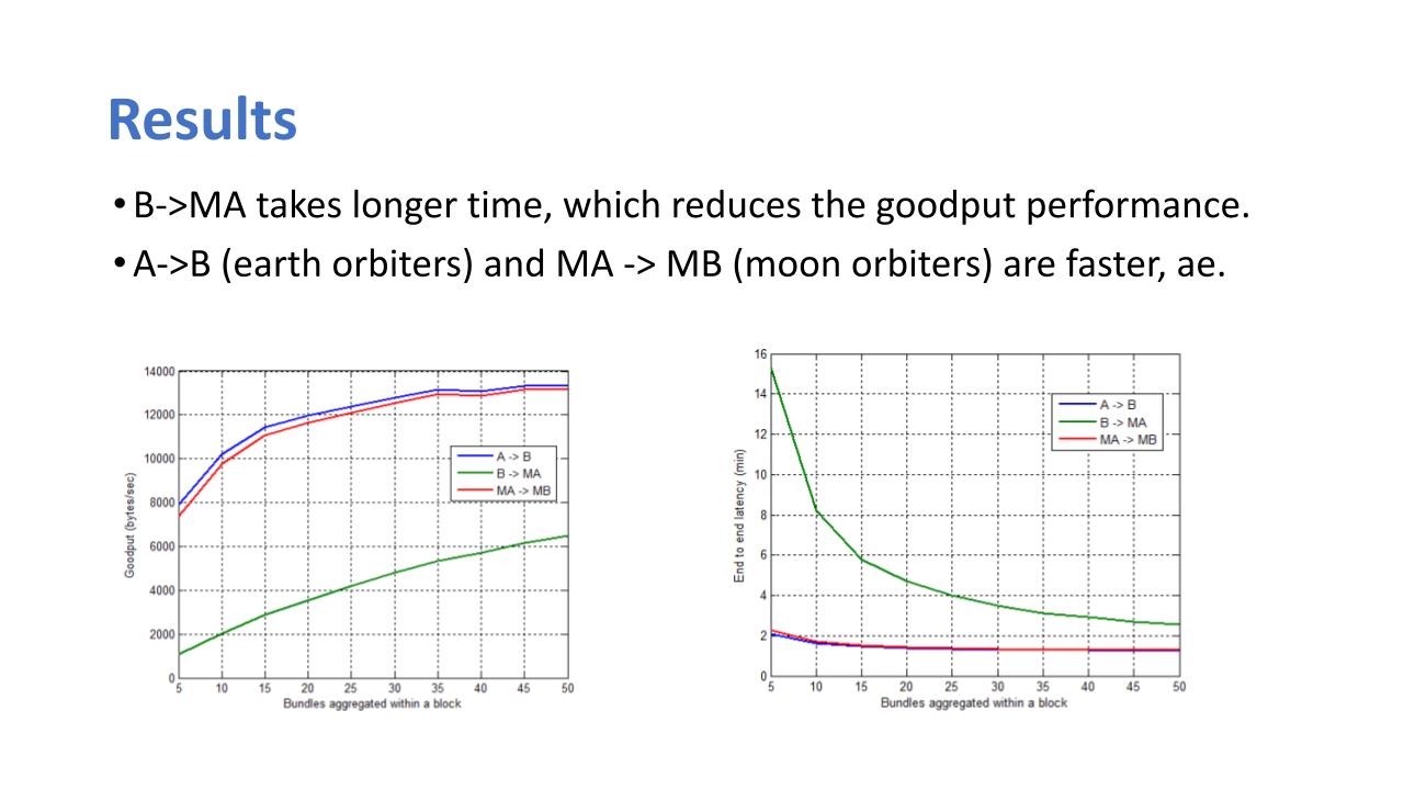 |
After evaluation, the results show that the B to MA hop takes longer time, which reduces the good put performance while the hops A to B and MA to MB are faster respectively. This implementation was done without any propagation loss or error probability because our aim was to see the application and how best it relates as opposed to the TCP network.
As seen in the figure each bundle was aggregated from 5 to 50 at rate of 5, we increased our bundle aggregation. Considering the good put, from 8000 bytes per second at the fifth bundle of hop A-B, it increases to 13 000 bytes per second approximately at the 50th bundle aggregation This shows that bundle aggregation for data transmission helps to reduce the latency right. Same is also seen at the end-to-end latency.
|
|
ICACT20240287 Slide.17
[Big slide for presentation]
|
Chrome Text-to-Speach Click!! |
 |
Results and Conclusion
|
|
ICACT20240287 Slide.16
[Big slide for presentation]
|
Chrome Text-to-Speach Click!! |
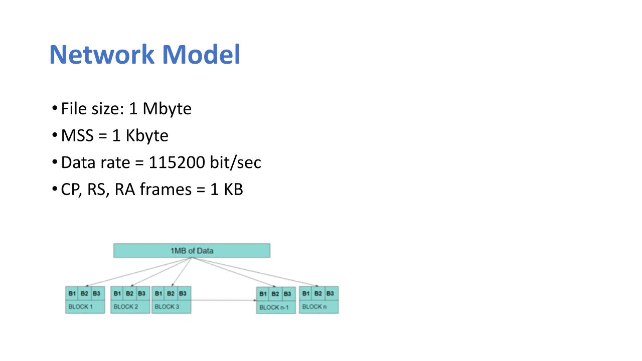 |
In the network model, we used the file size one megabyte and the maximum segment size 1 kilobyte. Data rate was 115,200 bits per second. The checkpoint, the report segment and the report acknowledgement frames each have the 1 kilobyte size in our implementation.
|
|
ICACT20240287 Slide.15
[Big slide for presentation]
|
Chrome Text-to-Speach Click!! |
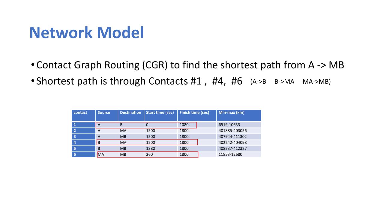 |
For the contact plan in Table, we run CGR to find the shortest path from source node A to destination node MB by implementing the algorithm. The shortest path is found as through contacts #1, #4 and #6, A→B, B→MA and MA→MB. In this route, the longest path in terms of propagation delay is contact #9 with 0.15 sec
|
|
ICACT20240287 Slide.14
[Big slide for presentation]
|
Chrome Text-to-Speach Click!! |
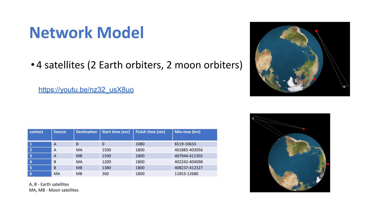 |
We implement the network model using four satellites as described in the previous slide. The source the router and the destination are all satellites and for this experiment we have 4 satellites (Two Earth Orbiter, A and B and Two Moon Orbiters, MA and MB) each of which have their contact plan as described.
The table shows the contact plan we obtained for a duration of 1800 secs, where nodes A and B are the Earth satellites, MA and MB are the Moon satellites. In the table, for example, the first row shows the first contact between nodes A and B; contact starts at 0 sec and lasts for 1080 secs. The average distance between A and B during this contact is 8,576km, which corresponds to the propagation delay of 0.018 sec.
|
|
ICACT20240287 Slide.13
[Big slide for presentation]
|
Chrome Text-to-Speach Click!! |
 |
Network Model
|
|
ICACT20240287 Slide.12
[Big slide for presentation]
|
Chrome Text-to-Speach Click!! |
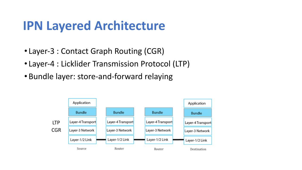 |
The Delay/Disruption Tolerant Network (DTN) architecture as shown in the figure is intended to deal with the interruptions and significant delays that come with space communications. DTN uses a store-and-forward transmission technique with optional custody transfer, which allows data to be transferred in small bundles and stored at intermediate nodes until a link becomes available.
The Bundle Protocol (BP) is a DTN stack protocol that provides custody-based data transport in space communications. LTP augments BP by assisting in data loss over space channels via heavy retransmission, hence minimizing the impacts of severe data loss.
In this study, we present a method of bundle aggregation with optimal delivery time in a multi-hop scenario. Several PC-based tests were carried out considering the distance between nodes, the contact time and error rate caused by several factors.
|
|
ICACT20240287 Slide.11
[Big slide for presentation]
|
Chrome Text-to-Speach Click!! |
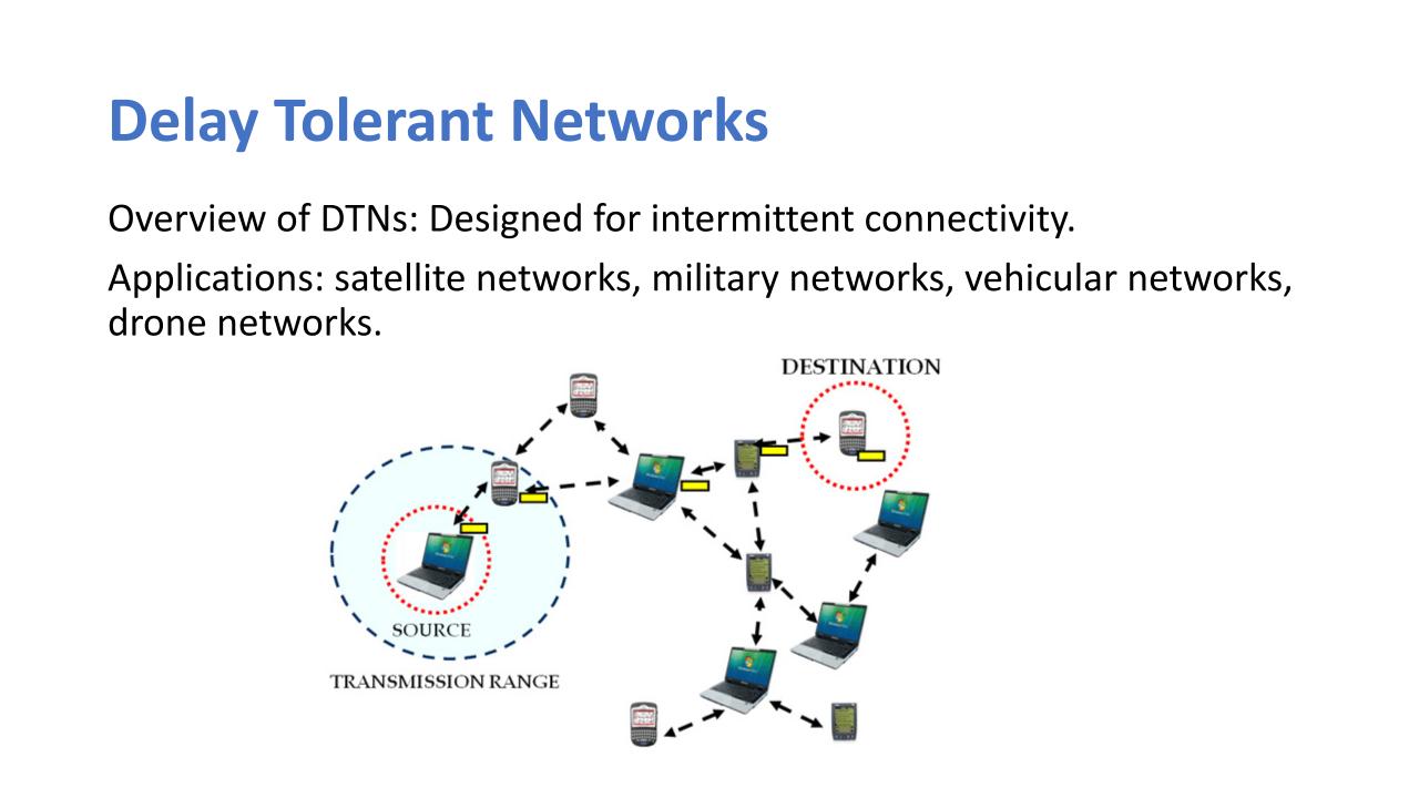 |
In an overview of the delay tolerant network, it is designed for intermittent connectivity. Its applications are in satellite networks military networks, vehicular networks and also drone application which is the unmanned aerial vehicle UAV
|
|
ICACT20240287 Slide.10
[Big slide for presentation]
|
Chrome Text-to-Speach Click!! |
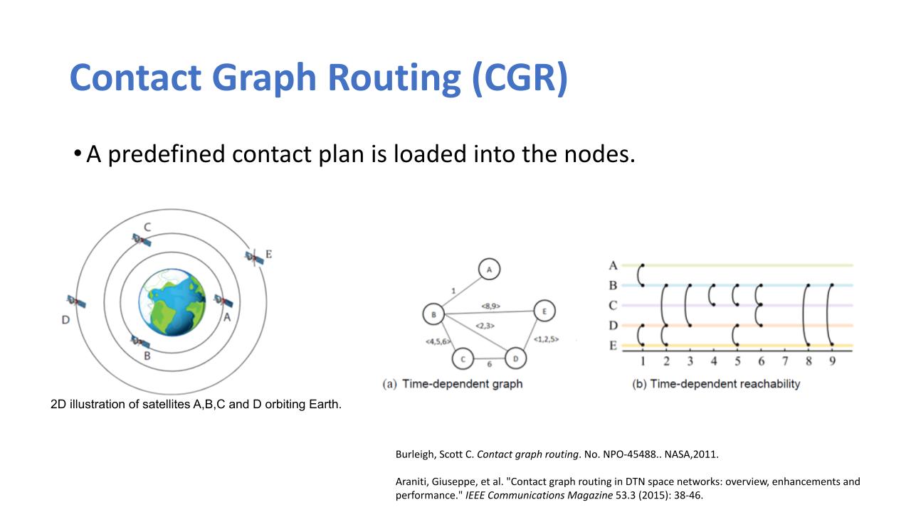 |
Now, going further to explain the contact graph routing. The contact graph routing, helps to determine the shortest path to follow for sending or transmitting data. Here you can see we have several satellites. This is a 2D illustration of satellites, A, B, C, and D orbiting the Earth, and each of them have a contact plan. So from here you can see, that all the contacts are time dependent. Being time dependent, there's a predefined contact plan meaning that it is not a probabilistic approach, hence the reason we extracted the real-time location of the satellites and it being a deterministic approach. The CGR relies on adapted Dijkstra’s shortest path algorithm. This algorithm computes a route from a source to a target node using a contact graph that is based on a contact plan. Each vertex in the contact graph represents connectivity period between two nodes. Two vertices are connected by a directed edge if the end of the earlier contact matches the start of the next contact. The computed route is a sequence of contacts from the source to the destination.
|
|
ICACT20240287 Slide.09
[Big slide for presentation]
|
Chrome Text-to-Speach Click!! |
 |
Contact Graph Routing (CGR)
|
|
ICACT20240287 Slide.08
[Big slide for presentation]
|
Chrome Text-to-Speach Click!! |
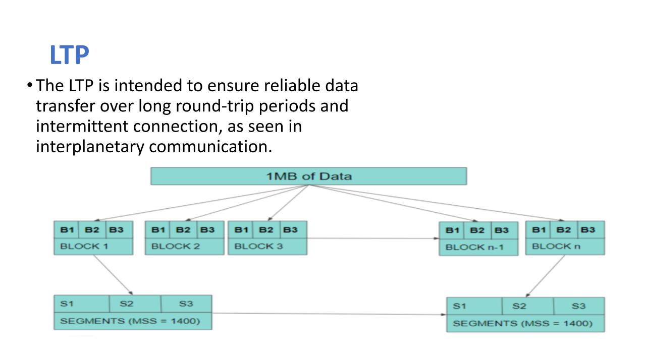 |
A method of bundle aggregation is applied to determine the good put and latency of file transfer using a multi-hop scenario. Bundle aggregation allows for bundles to be transferred in batch or single pairs. The file is split into a number of bundles and then these bundles are either joined in unity to form a block or number of blocks (from ith block to nth block) or in pairs/aggregated pairs. In this study, the bundle aggregation starts from a bundle size of three to a nth number of bundles in the block. We transmitted one megabyte of data at initial simulation. From the figure, we see that the one megabyte of data was split into several blocks and then these blocks have what we call bundles. These are the bundles that are being stored in the bundle protocol, so we have block 1, block 2, block 3 down to block n. Each block has bundles depending on the amount of bundles you want to set in a block. Furthermore, blocks are then divided into several segments, obeying the set guidelines for DTN architecture and for transfer in inter-satellite connection or connectivity. The blocks are split to segment, and then the maximum segment size we used was 1,400bytes as opposed to the regular MSS in TCP which is 1460bytes
|
|
ICACT20240287 Slide.07
[Big slide for presentation]
|
Chrome Text-to-Speach Click!! |
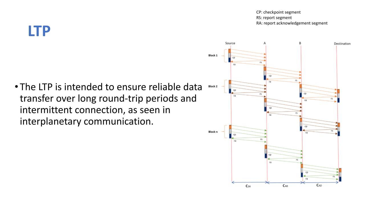 |
The LTP works with the concept of retransmission and it is the transport protocol which lies on layer four of the DTN architecture. It is intended to ensure reliable transmission of data transfer over long round trip periods amidst intermittent condition as seen in the interplanetary communication. From the figure it is seen that we have four nodes; Source, Destination, node A and node B in what call the multi-hop scenario. This scenario works such that data goes through several hops starting from the source through nodes A and B before it gets to the destination. Following the transmission of a block, the sender transmits a checkpoint (CP) segment. The receiver checks for segment loss within the block after receiving the CP segment and sends a report segment (RS) to the sender to indicate any loss. If no loss is discovered, the receiver acknowledges the sender cumulatively with RA; otherwise, RS tells the sender of the missing data, forcing the sender to retransmit, followed by another CP at the end of the transmission. To ensure delivery, both CP and RS segments are sent with a timer in LTP. They are then retransmitted if there is a timeout. This process is repeated at each node until the data finally gets to the destination.
In our study, we performed initial simulations based on a no error policy/ no error probability so all that we can determine the rate at which data is transmitted at a near perfect condition.
|
|
ICACT20240287 Slide.06
[Big slide for presentation]
|
Chrome Text-to-Speach Click!! |
 |
Licklider Transmission Protocol (LTP)
|
|
ICACT20240287 Slide.05
[Big slide for presentation]
|
Chrome Text-to-Speach Click!! |
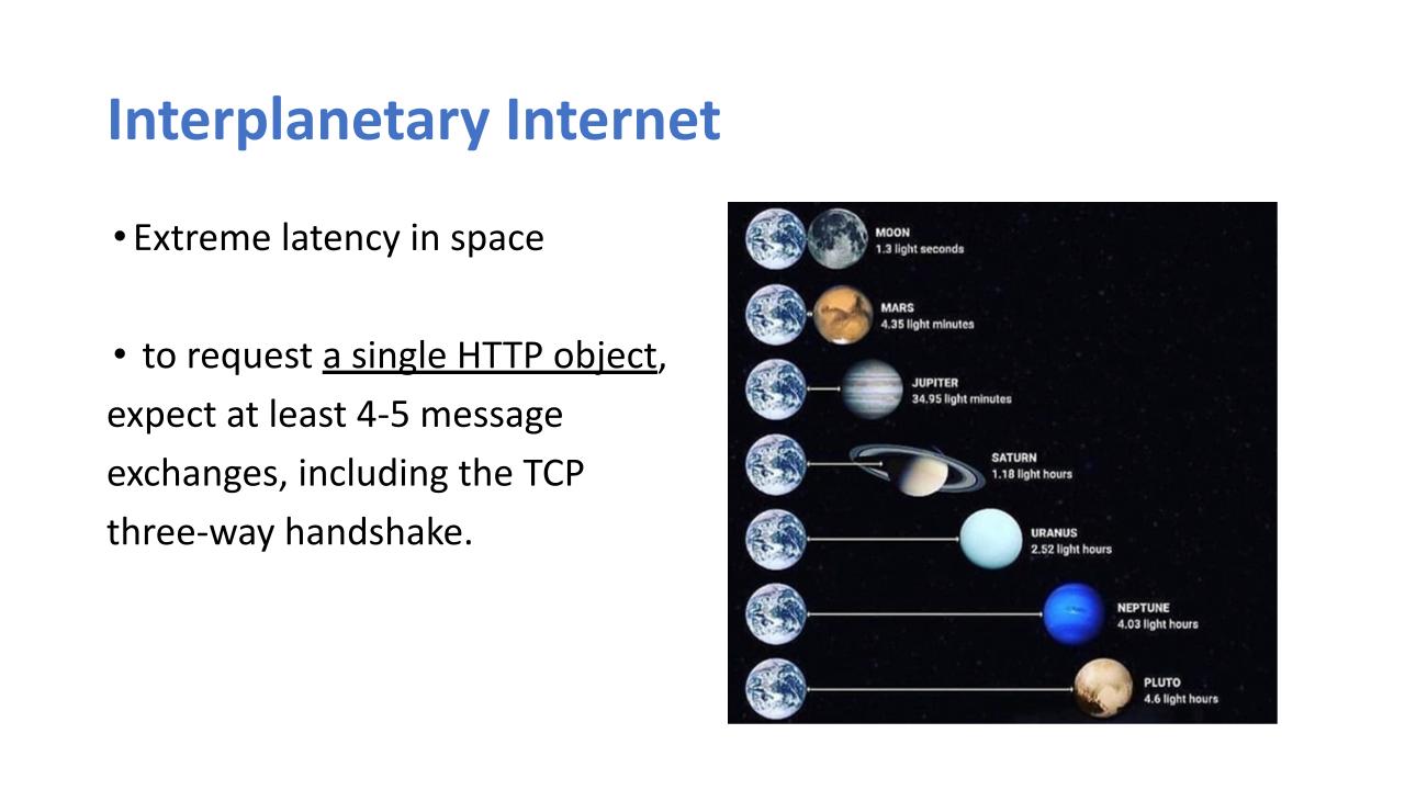 |
Due to the vast distance between space objects and several other factors, extreme latency is inevitable thus defeating the purpose for a TCP protocol in space network. An instance would be a request for a single HTTP object which will require a three-way handshake. The three-way handshake between a client and the server includes the synchronizing (SYN) of both nodes and the acknowledgement (ACK) i.e. SYN, SYN-ACK and ACK. At such we expect to see at least four to five message exchanges for the HTTP request.
|
|
ICACT20240287 Slide.04
[Big slide for presentation]
|
Chrome Text-to-Speach Click!! |
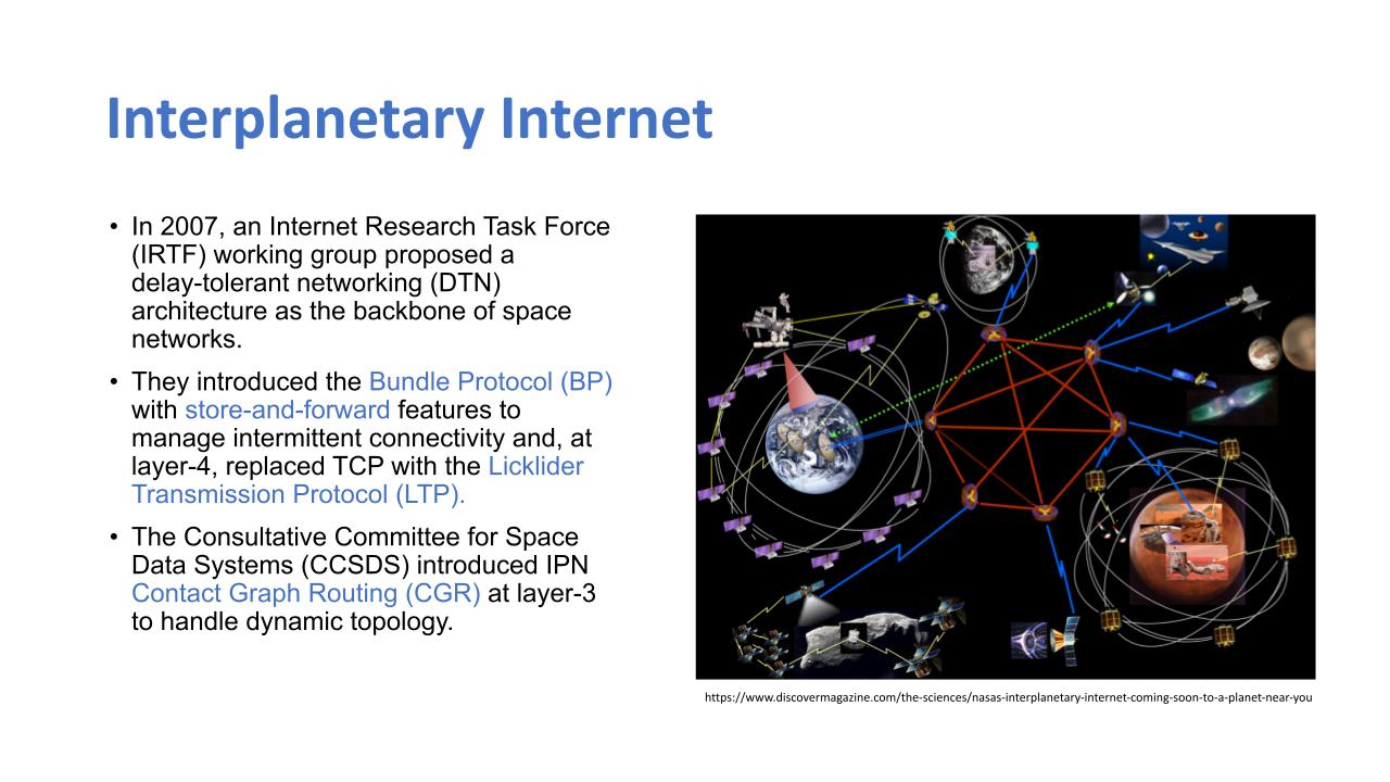 |
With the traditional transport and network layer which we are used to here on earth, the technologies are not suitable for space networks, especially for interplanetary networks. These challenges actually have resulted to several novel approaches intended to address the challenges of space network as earlier mentioned in the previous slide. In 2007 an internet research task force (IRTF) proposed a delay tolerance network as the backbone of space network which is an
improvement of the open systems interconnection model which is the OSI model which we're quite familiar with as the regular traditional network. Here, the study aimed to restructure existing model so as to achieve the DTN architecture as we now know it to be. This restructuring involves the introduction of the bundle protocol which has the store and forward features. The store forward features actually helps to keep/hold in message till when there is a line of sight or when the receiver is actually in sight for them to receive the data which we refer to as the contact time. Instead of having to send the message as opposed to the regular transmission on the traditional network the bundle protocol helps to store the message until when there is contact between both nodes before it then transmits the data. The transmission control protocol also which is the TCP protocol at the layer 4 of the traditional network was replaced with the licklider transmission protocol which was used to reduce the acknowledgement traffic over the network. Subsequently the consultative committee for space data systems which is the CCSDS introduced the IPN contact graph routing at the layer 3 to avoid dynamic topology and find the sources and also it helps to find the shortest path in space unlike the traditional OSPF routing protocol which we are used. The contact graph routing being an improvement of the OSPF deals with a deterministic approach for data transmission. Once there is a contact between two nodes, a link is set and the bundles are forwarded, without which bundles will be stored at the sending node until a contact is made. All these restructuring combine to give what we now know as the delay tolerance network architecture
|
|
ICACT20240287 Slide.03
[Big slide for presentation]
|
Chrome Text-to-Speach Click!! |
 |
Interplanetary Internet
|
|
ICACT20240287 Slide.02
[Big slide for presentation]
|
Chrome Text-to-Speach Click!! |
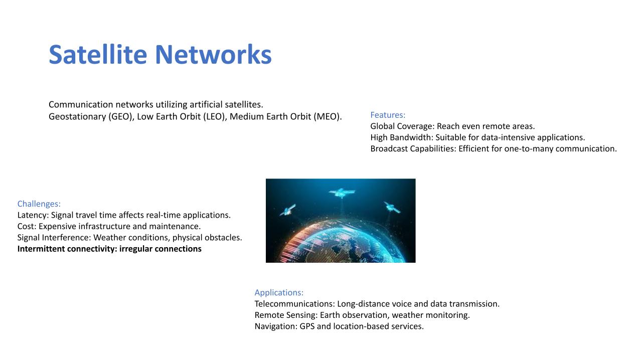 |
For an effective communication to take place, two bodies are required, one for sending and then the other for receiving. This same characteristic is a common factor in satellite communication. Not only is it required for two satellites to communicate effectively, it can also be that one satellite communicates with many, reaching global coverage especially remote areas also. Satellites have high bandwidth capabilities which is suitable for data intensive applications. In this work, we make reference to communication network which utilizes artificial satellites. Here, we continue to consider the satellite constellation consisting of two low earth-orbit satellites, which is the LEO satellite, one medium earth-orbit satellite, which is the MEO satellite, and then one geostationary-orbit satellite which is the GEO satellite, each of which the real-time location was obtained from CelesTrak, and then we visualized it using our tool which we developed. It is also worthy to note the challenges associated with satellite communication, which include latency, cost, signal interference, and intermittent connectivity. These are the major challenges that are associated with satellite communication. The signal interference could be due to the distance, weather conditions or physical obstacles while the cost of maintaining such expensive infrastructures also pose an issue. We see also that the signal travel time affects real-time applications were a quick response is needed for operations. Signal interference may be probably due to irregularities of movement or space debris or whatever you may have in space or along the way of the line of sight.
|
|
ICACT20240287 Slide.01
[Big slide for presentation]
|
Chrome Text-to-Speach Click!! |
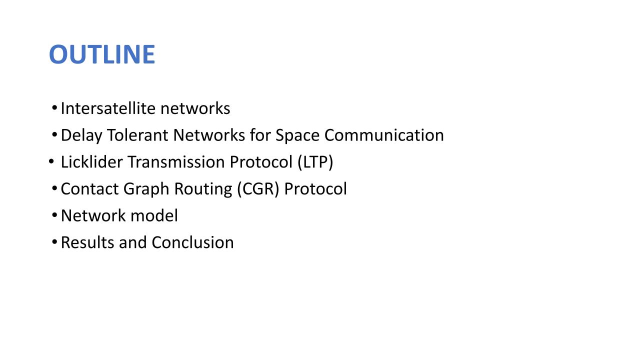 |
This presentation is sectioned into different parts namely; inter-satellite networks, delay-tolerance networks for space communication, contact graph routing protocol, licklider transmission protocol which is the LTP, network model, and finally result and conclusion.
|
|
ICACT20240287 Slide.00
[Big slide for presentation]
|
Chrome Text-to-Speach Click!! |
 |
Hi everybody, my name is Israel Ehile. Our team members are mainly from the School of Engineering and Digital Sciences from Nazarbayev University, namely Dr. Refik Caglar Kizilirmak, Israel Ehile, Bekzat Kabdrashev and Sergey Khvan from the Department of Electrical and Computer Engineering. I am very glad to have this opportunity to share the work of our team. This presentation is centered around proffering a solution to the higher latency in inter-satellite connection in space communication hence, titled Enhancing Inter-Satellite Data-Relay in Dynamic Space Communication.
|
















