 ICACT20220165 Slide.36
[Big slide for presentation]
[YouTube] |
Chrome Text-to-Speach Click!! |
 |
Thank you for making it till this point of the presentation. I will be happy for any feedback and to answer any questions that you may have.
|
|
ICACT20220165 Slide.35
[Big slide for presentation]
[YouTube] |
Chrome Text-to-Speach Click!! |
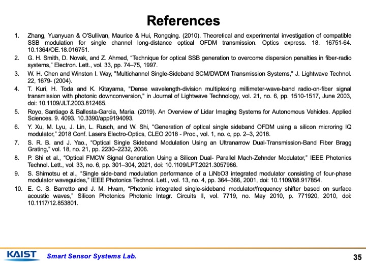 |
These are the references used in the presentation.
|
|
ICACT20220165 Slide.34
[Big slide for presentation]
[YouTube] |
Chrome Text-to-Speach Click!! |
 |
In future, we plan to verify the remaining two techniques with experimentation and we plan to perform experiments using higher modulation frequencies.
|
|
ICACT20220165 Slide.33
[Big slide for presentation]
[YouTube] |
Chrome Text-to-Speach Click!! |
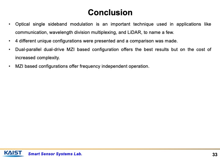 |
The conclusion can be made with the following points.
Optical single sideband modulation is an important technique used in applications like communication, wavelength division multiplexing, and LiDAR, to name a few.
4 different unique configurations were presented and a comparison was made.
Dual-parallel dual-drive MZI based configuration offers the best results but on the cost of increased complexity.
MZI based configurations offer frequency independent operation
|
|
ICACT20220165 Slide.32
[Big slide for presentation]
[YouTube] |
Chrome Text-to-Speach Click!! |
 |
To summarize the experimental results, demonstration of proof concept of single sideband modulation presented in the simulations was done.
|
|
ICACT20220165 Slide.31
[Big slide for presentation]
[YouTube] |
Chrome Text-to-Speach Click!! |
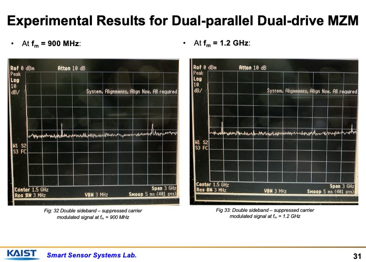 |
Some further results are presented here at frequencies 900 MHz and 1.2 GHz. The peaks of two sidebands drift further apart while the carrier remains suppressed. It also proves the concept of using it as an optical frequency shifter.
|
|
ICACT20220165 Slide.30
[Big slide for presentation]
[YouTube] |
Chrome Text-to-Speach Click!! |
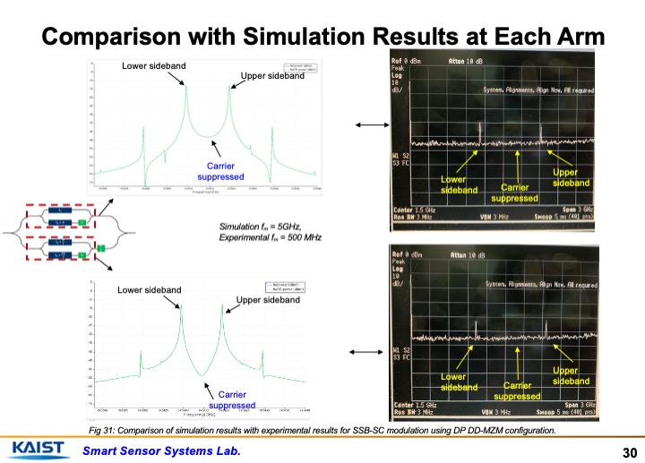 |
As can be seen in the figure, the output of both sub arms match the simulation results. The carrier is suppressed and we have upper and lower sidebands.
|
|
ICACT20220165 Slide.29
[Big slide for presentation]
[YouTube] |
Chrome Text-to-Speach Click!! |
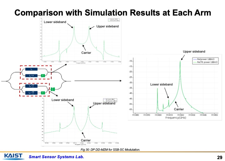 |
To prove the concept of the dual-parallel dual-drive MZM, we have tested each of the sub arms of the MZM configuration. As can be seen from the figure, both of them give a double sideband suppressed carrier signal as output, which combines at the output and due to phase shift in one of the sidebands of the two signals, just one sideband survives. This simulation result can be matched with experiment to get an idea of the proof of concept.
|
|
ICACT20220165 Slide.28
[Big slide for presentation]
[YouTube] |
Chrome Text-to-Speach Click!! |
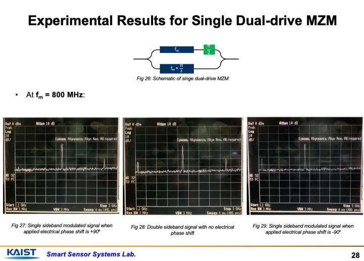 |
Some more results can be seen at the modulating frequency of 800 MHz. In Fig 27, the lower sideband is suppressed because of application of electrical phase shift of +90 degrees. In Fig 29, the higher order sideband is suppressed because of application of electrical phase shift of -90 degrees, as expected and as matched with the simulation.
|
|
ICACT20220165 Slide.27
[Big slide for presentation]
[YouTube] |
Chrome Text-to-Speach Click!! |
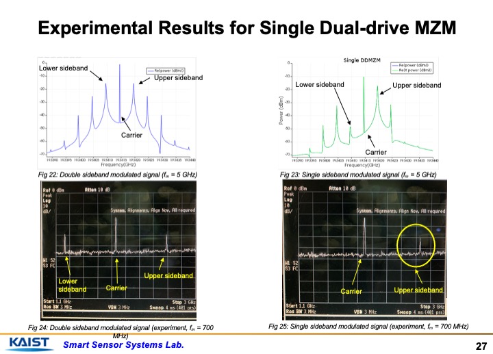 |
The experimental results for the single dual-drive MZM are presented in the right figure. The left figure shows a double sideband signal. It can be seen that both sidebands and carrier are present in the left picture of RF spectrum analyzer but in the right figure, the lower sideband has been suppressed. Modulating frequency in experiment used is 700 MHz due to the resolution limitation of source and analyzer. The higher order sidebands are not visible because of the added noise from coupler and photodiode.
|
|
ICACT20220165 Slide.26
[Big slide for presentation]
[YouTube] |
Chrome Text-to-Speach Click!! |
 |
Experimental results will be presented now.
|
|
ICACT20220165 Slide.25
[Big slide for presentation]
[YouTube] |
Chrome Text-to-Speach Click!! |
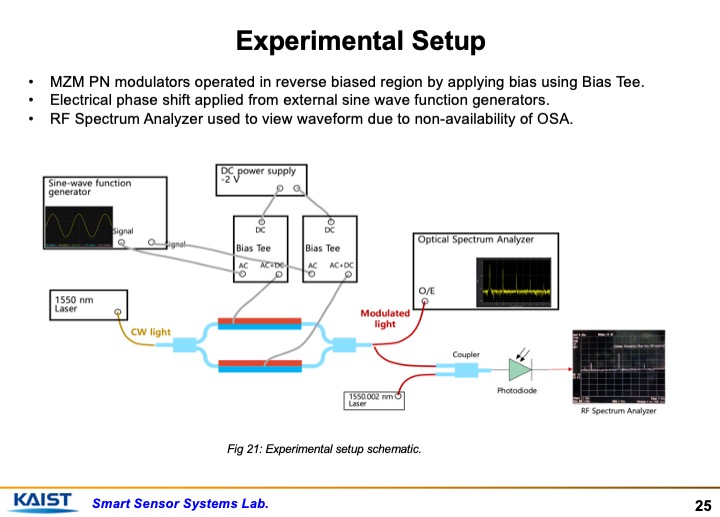 |
The experimental setup used to test the configuration is shown in the figure. Carrier frequency from a 1550 nm laser source and RF signals are generated by sine-wave function generator. It is passed through Bias tee and applied to the modulating arms of MZM. Due to unavailability of an optical spectrum analyzer, the output light from MZM has been down-converted to a frequency that is observable in RF spectrum analyzer using coupler and another laser source of 1550.002 nm.
|
|
ICACT20220165 Slide.24
[Big slide for presentation]
[YouTube] |
Chrome Text-to-Speach Click!! |
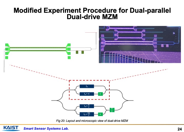 |
One of the dual-parallel schemes have been tested using just one of the sub arms of the total configuration due to the fact that it is still an ongoing research work and due to unavailability of the fabricated chip.
|
|
ICACT20220165 Slide.23
[Big slide for presentation]
[YouTube] |
Chrome Text-to-Speach Click!! |
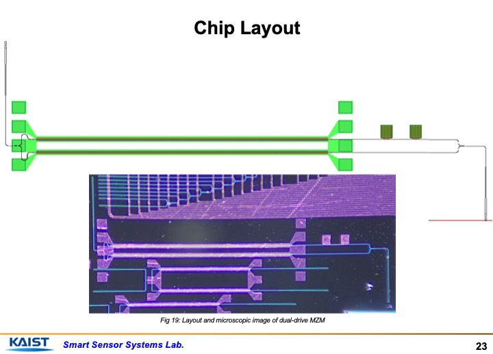 |
This is the layout and microscopic image of the MZM structure.
|
|
ICACT20220165 Slide.22
[Big slide for presentation]
|
Chrome Text-to-Speach Click!! |
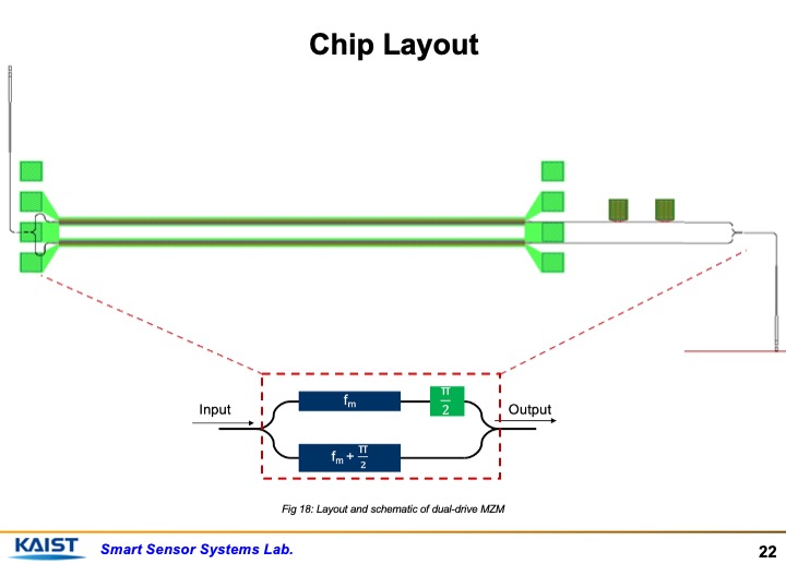 |
This is the layout of the MZM structure that we used to test the single dual-drive MZM.
|
|
ICACT20220165 Slide.21
[Big slide for presentation]
|
Chrome Text-to-Speach Click!! |
 |
Experimental Setup
|
|
ICACT20220165 Slide.20
[Big slide for presentation]
[YouTube] |
Chrome Text-to-Speach Click!! |
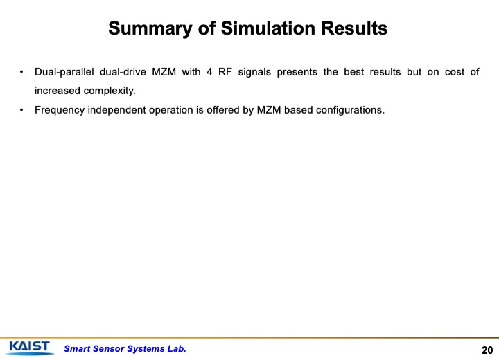 |
To provide the summary of the simulation results, Dual-parallel dual-drive MZM with 4 RF signals presents the best results but on cost of increased complexity.
Frequency independent operation is offered by MZM based configurations.
|
|
ICACT20220165 Slide.19
[Big slide for presentation]
|
Chrome Text-to-Speach Click!! |
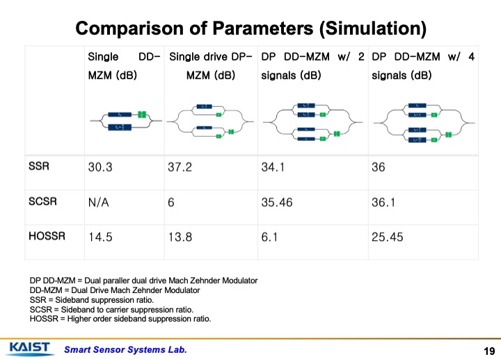 |
A comparison of all the schemes has been provided in this table. It can be seen that the dual-parallel dual-drive MZM configuration offers the best results but the complexity increases specially in terms of applying 4 RF phase shifted signals.
|
|
ICACT20220165 Slide.18
[Big slide for presentation]
|
Chrome Text-to-Speach Click!! |
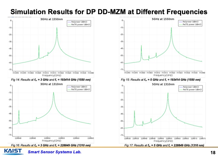 |
These figures show the main advantage of using an MZI based configuration for SSB modulation. The results of dual-parallel dual-drive MZM configuration are shown. In the Fig 14 and 15, the carrier frequency is 193414 GHz (1550nm) and the modulation frequency is 3GHz and 5 GHz respectively.
In the bottom figures of 16 and 17, the carrier wavelength is 1310nm and the modulation frequency is 3GHz and 5 GHz respectively.
In all the cases, it can be seen that similar results are obtained, which prove that its operation is independent of the frequency used.
|
|
ICACT20220165 Slide.17
[Big slide for presentation]
|
Chrome Text-to-Speach Click!! |
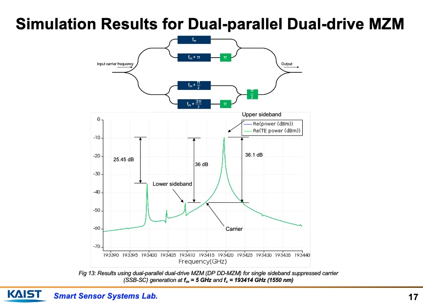 |
These are the simulation results for dual-parallel dual-drive configuration with 4 RF phase shifted signals. The phase shift from top to bottom is of 0, 180, 90 and 270 degrees respectively. It has upper sideband to carrier suppression of 36.1 dB, upper sideband to lower order sideband suppression of 36 dB and an upper sideband to higher order sideband suppression of 25.45 dB. This configuration provides the best results but on the cost of higher complexity.
|
|
ICACT20220165 Slide.16
[Big slide for presentation]
|
Chrome Text-to-Speach Click!! |
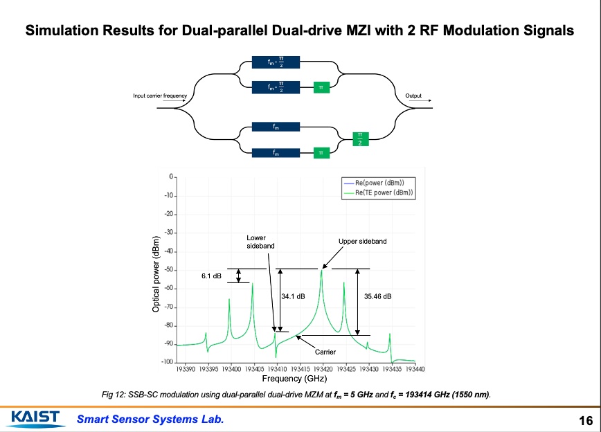 |
These are the simulation results for dual-parallel dual-drive configuration with 2 RF 90 degrees phase shifted signals. It has upper sideband to carrier suppression ratio of 35.46 dB, upper sideband to lower order sideband suppression of 34.1 dB and an upper sideband to higher order sideband suppression of 6.1 dB. One drawback is that the overall loss is quite large for all the wavelengths/frequencies.
|
|
ICACT20220165 Slide.15
[Big slide for presentation]
|
Chrome Text-to-Speach Click!! |
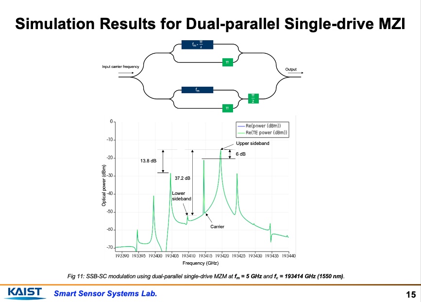 |
These are the simulation results for dual-parallel single-drive configuration. It has upper sideband to carrier suppression ratio of 6 dB,upper sideband to lower order sideband suppression of 37.2 dB and an upper sideband to higher order sideband suppression of 13.8 dB.
|
|
ICACT20220165 Slide.14
[Big slide for presentation]
|
Chrome Text-to-Speach Click!! |
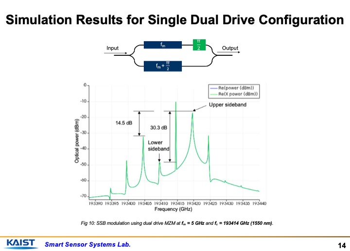 |
These are the simulation results for single dual-drive configuration. It has no sideband to carrier suppression but it has upper sideband to lower order sideband suppression of 30.3 dB and a upper sideband to higher order sideband suppression of 14.5 dB.
|
|
ICACT20220165 Slide.13
[Big slide for presentation]
|
Chrome Text-to-Speach Click!! |
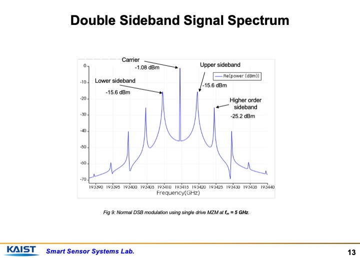 |
To give you a reference, a double sideband signal looks like this. It has a carrier at the center, upper and lower order sidebands and higher order sidebands as well.
|
|
ICACT20220165 Slide.12
[Big slide for presentation]
|
Chrome Text-to-Speach Click!! |
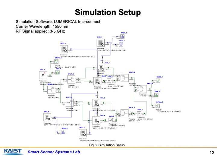 |
This is just a picture of one of the schemes being implemented in simulation. We used LUMERICAL Interconnect and the Carrier Wavelength was 1550 nm while the RF Signal applied was 3-5 GHz.
|
|
ICACT20220165 Slide.11
[Big slide for presentation]
|
Chrome Text-to-Speach Click!! |
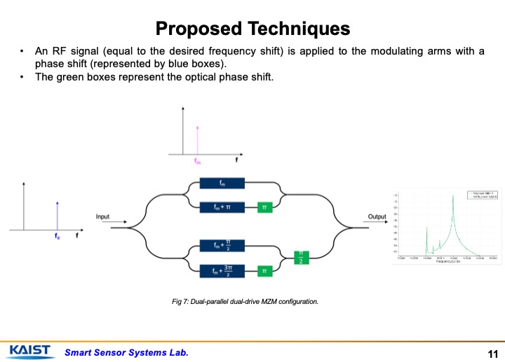 |
This slide just provides the framework of the use of the schemes. Input is added by a carrier frequency of 1550 nm, RF signal is applied to the PN phase shifters at blue boxes and we get a single sideband modulated signal at the output.
|
|
ICACT20220165 Slide.10
[Big slide for presentation]
|
Chrome Text-to-Speach Click!! |
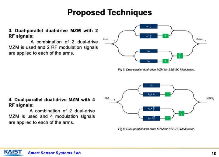 |
The third scheme is using Dual-parallel dual-drive MZM with 2
RF signals. A combination of 2 dual-drive MZM is used and 2 RF modulation signals are applied to each of the arms.
The fourth one is by making the use of Dual-parallel dual-drive MZM with 4 RF phase shifted signals. A combination of 2 dual-drive
MZM is used and 4 modulation signals are applied to each of the arms.
|
|
ICACT20220165 Slide.09
[Big slide for presentation]
|
Chrome Text-to-Speach Click!! |
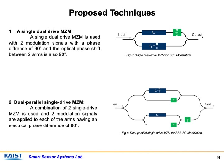 |
These are the techniques that have been presented in the paper and that will be presented in this presentation.
First one is using single dual-drive MZM. A single dual drive MZM is used with 2 modulation signals with a phase
diffrence of 90° and the optical phase shift
between 2 arms is also 90°.
The second one is using Dual-parallel single-drive MZM. A combination of 2 single-drive MZM is used and 2 modulation signals
are applied to each of the arms having an electrical phase difference of 90°.
One thing to note here is that blue boxes represent electrical RF signal and green boxes represent optical phase shift.
|
|
ICACT20220165 Slide.08
[Big slide for presentation]
|
Chrome Text-to-Speach Click!! |
 |
Proposed Techniques and Simulation Results
|
|
ICACT20220165 Slide.07
[Big slide for presentation]
|
Chrome Text-to-Speach Click!! |
 |
In this work, Single Sideband signal generation techniques are presented using Mach-Zehnder Interferometers. 4 schemes are presented and compared. The proposed schemes include configurations involving dual-drive and dual-parallel Mach-Zehnder Modulators.
|
|
ICACT20220165 Slide.06
[Big slide for presentation]
|
Chrome Text-to-Speach Click!! |
 |
These are some mentions of the past works done in this domain. Single dual-drive MZM has been used to produce Optical Single Sideband (OSSB) signal. Ring modulators have been used to reduce device footprint. Optical filter has been used to obtain suppressed carrier SSB signal. Dual parallel mach-zehnder modulators have been used. Surface acoustic waves have been used for the generation of SSB signal.
|
|
ICACT20220165 Slide.05
[Big slide for presentation]
|
Chrome Text-to-Speach Click!! |
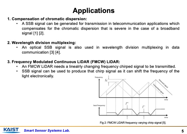 |
To name a few application of optical single sideband modulation, it is used in telecommunication for Compensation of chromatic dispersion and wavelength division multiplexing. It is also used for chirp signal generation of an FMCW LiDAR. FMCW LiDAR needs a constantly changing chirp signal which can be generated conveniently using SSB technique by just changing the input electrical frequency of the RF wave.
|
|
ICACT20220165 Slide.04
[Big slide for presentation]
|
Chrome Text-to-Speach Click!! |
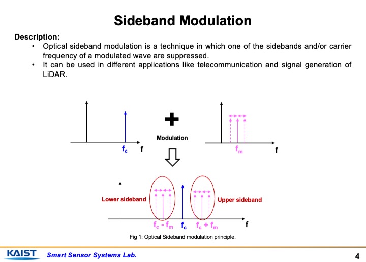 |
This slide provides a basic introduction about sideband modulation. Optical sideband modulation is a technique in which one of the sidebands and/or carrier frequency of a modulated wave are suppressed.
It can be used in different applications like telecommunication and signal generation of
LiDAR.
It can be seen from the figure that changing the modulation frequency, we can change the frequency of the upper and lower sidebands. Suppressing undesired sideband and carrier can offer us uses of the desired sideband in our desired applications.
|
|
ICACT20220165 Slide.03
[Big slide for presentation]
|
Chrome Text-to-Speach Click!! |
 |
Starting with the introduction...
|
|
ICACT20220165 Slide.02
[Big slide for presentation]
[YouTube] |
Chrome Text-to-Speach Click!! |
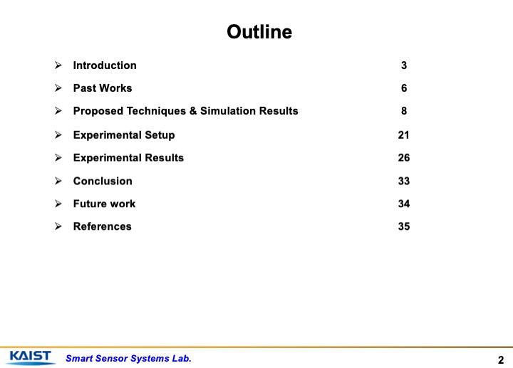 |
This is the outline that I will be following. I will start with introduction, then explain a bit about past works done. Then I will move on to proposed techniques and simulation results. I will explain experimental setup and results. At the end, I will conclude with conclusion, future work and references.
|
|
ICACT20220165 Slide.01
[Big slide for presentation]
[YouTube] |
Chrome Text-to-Speach Click!! |
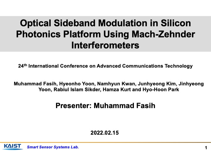 |
Hello everyone. My name is Muhammad Fasih and I am a student at KAIST and I work at Smart Sensor and Systems Lab. I am going to be presenting today about Optical Sideband Modulation in Silicon Photonics Platform Using Mach-Zehnder Interferometers.
|
















