ICACT20220362 Slide.18
[Big slide for presentation]
[YouTube]
ICACT20220362 Slide.18
[Big slide for presentation]
[YouTube] |
Chrome Text-to-Speach Click!! Click!! |
 |
Thanks for your attention! Now! Floor is open for QnA. Welcome any comment or question.
|
|
ICACT20220362 Slide.17
[Big slide for presentation]
[YouTube] |
Chrome Text-to-Speach Click!! |
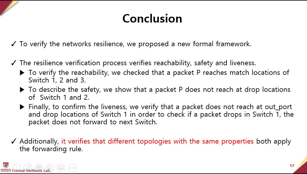 |
To verify the networks resilience, we proposed a new formal framework.
The resilience verification process verifies reachability, safety and liveness.
To verify the reachability, we checked that a packet P reaches match locations of Switch 1, 2 and 3.
To describe the safety, we show that a packet P does not reach at drop locations of Switch 1 and 2.
Finally, to confirm the liveness, we verify that a packet does not reach at out_port and drop locations of Switch 1 in order to check if a packet drops in Switch 1, the packet does not forward to next Switch.
Additionally, it verifies that different topologies with the same properties both apply the forwarding rule.
|
|
ICACT20220362 Slide.16
[Big slide for presentation]
[YouTube] |
Chrome Text-to-Speach Click!! |
 |
Conclusion
|
|
ICACT20220362 Slide.15
[Big slide for presentation]
[YouTube] |
Chrome Text-to-Speach Click!! |
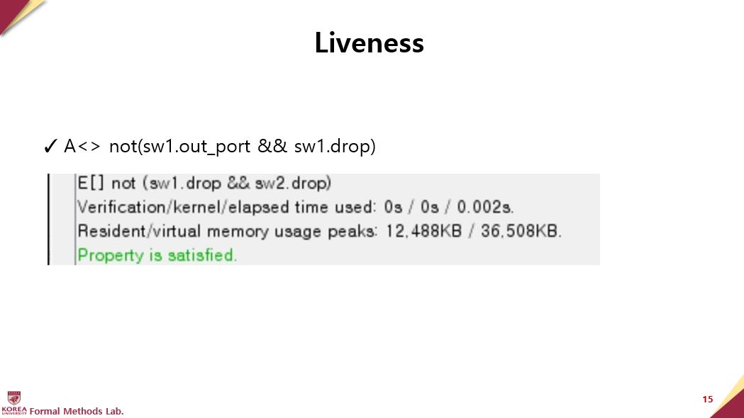 |
Liveness properties are based on the concept that “something will eventually happen.”
We verified “A<> not(sw1.out_port && sw1.drop)”
The figure is also verification results for “Property is satisfied.” This means that a packet P on all path could not go out_port and drop locations of Switch 1 in order to liveness property.
|
|
ICACT20220362 Slide.14
[Big slide for presentation]
[YouTube] |
Chrome Text-to-Speach Click!! |
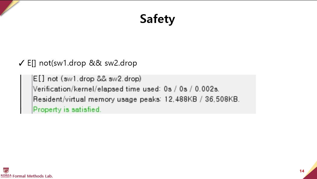 |
Safety properties are based on the concept that “something bad will never happen.” In UPPAAL, this is formulated positively, for example, something good is invariantly true.
The packets should not always be dropped.
Figure shows the verification results for “Property is satisfied.” On the other words, a packet P on a path should not be in the each drop locations of switches 1 and 2.
|
|
ICACT20220362 Slide.13
[Big slide for presentation]
[YouTube] |
Chrome Text-to-Speach Click!! |
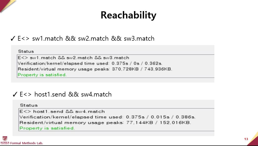 |
We express that some state satisfying P should be reachable using the path formula E<>P. The following formulae verify that a packet reaches the same destination for two different topologies: “E<> sw1.match && sw2.match && sw3.match “
First Figure show that verification results is “Property is satisfied.” In the other words, a packet P on a path reaches match locations of Switch 1, 2 and 3 on each topology in order to match the rule on flow table.
Next Figure is also verification results for “Property is satisfied.” It means that a packet P on a path reaches send location of Host1 and match location of Switch 4 on each topology. This shows that whether the packet sent from Host 1 matches Switch 4.
|
|
ICACT20220362 Slide.12
[Big slide for presentation]
[YouTube] |
Chrome Text-to-Speach Click!! |
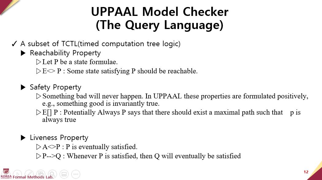 |
The query language of UPPAAL model Checker is a subset of TCTL(timed computation tree logic)
Verification attributes include reachability, safety, and liveness.
Reachability properties are used while designing a model to perform sanity checks and validate the basic behavior of the model.
Let P be a state formulae.
E<> P : Some state satisfying P should be reachable.
Safety is the property that “Something bad will never happen.”
In UPPAAL these properties are formulated positively, for example, something good is invariantly true.
Liveness is the property of “good things happen someday.”
A<>P : P is eventually satisfied.
P-->Q : Whenever P is satisfied, then Q will eventually be satisfied
|
|
ICACT20220362 Slide.11
[Big slide for presentation]
[YouTube] |
Chrome Text-to-Speach Click!! |
 |
Verification
|
|
ICACT20220362 Slide.10
[Big slide for presentation]
[YouTube] |
Chrome Text-to-Speach Click!! |
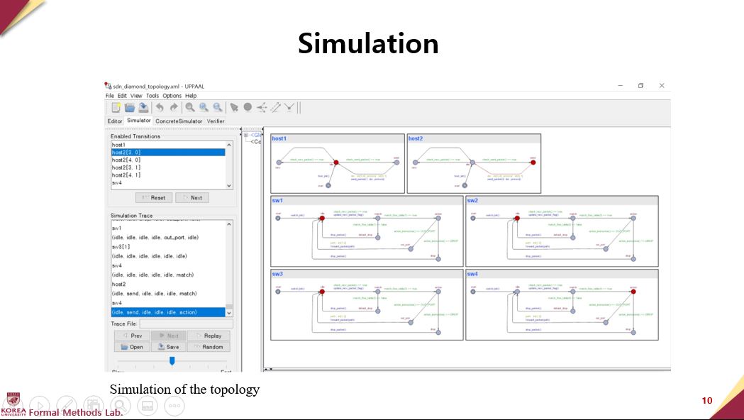 |
In our study, the verification framework specifies and verifies each property with TCTL [5]. The query language in TCTL consists of path formulae and state formulae. State formulae describe individual states, whereas path formulae quantify the paths or traces of a model. Path formulae can be classified for reachability, safety, and liveness. The formal framework that we propose verifies three properties in two different topologies. And simulation was also performed as shown in the Figure
|
|
ICACT20220362 Slide.09
[Big slide for presentation]
[YouTube] |
Chrome Text-to-Speach Click!! |
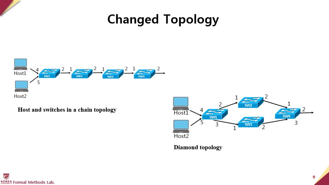 |
The network topology changes depending on the network environment. For instance, the topology can change from chain (Figure at the top) to diamond(Figure below). In Figure below, host 1 and host 2 forward the packet to sw1, then the topology is splited to sw2 and sw3. The packet also is forwarded from port 2 of sw1 to port1 of sw2 in the topology. Then sw1 forwards the packet to part 1 of sw3. The packet of sw2 and sw3 is forwarded to sw4.
|
|
ICACT20220362 Slide.08
[Big slide for presentation]
[YouTube] |
Chrome Text-to-Speach Click!! |
 |
The switch begins in an idle location in Figure 5; after a packet arrives at the switch, the packet matches the rule to the flow table's flow entry to determine the forwarding rule for the packet. The match location checks the flow table and finds a matching field. If the flow table has matching rules(match_flow_table(switch_id) == true), the packet goes to the action location. If the flow table does not have matching rules(match_flow_table(switch_id) ==false), it drops the packet. Switch modeling used the switch_init(), check_recv_packet(),update_recv_packet_flag(), match_flow_table(), action_instruction(), drop_packet(), and forward_packet() functions. The function switch_init() initializes a switch and adds a flow table. The function check_recv_packet() checks whether a packet is received. update_recv_packet_flag() updates the packet reception status. match_flow_table() checks whether the received packet has a matching entry in the flow table. If the packet is not in the flow table, it is dropped, and if it is in the flow table, it is executed as the specified action. The function action_instruction() checks whether the action matched in the flow table is OUT_PORT or DROP. The function forward_packet() forwards the packet and randomly processes the path.
|
|
ICACT20220362 Slide.07
[Big slide for presentation]
[YouTube] |
Chrome Text-to-Speach Click!! |
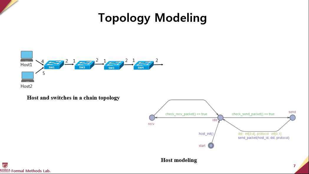 |
Switches can be connected in many different topologies. We start with a chain topology of two hosts and four switches in the network, as shown in Figure at the top
The host is the starting point for a packet. Each packet in the packet starts with the address of the origin and the address of the destination. The host checks the packet reception, transmission, and transmission possibilities. The functions used for host modeling are host_init(), check_recv_packet(), check_send_packet(), recv_update(), and send_packet(), shown in Figure below. The function host_init() initializes the host. The function check_recv_packet() checks whether the host receives a packet. The function recv_update() initializes after receiving a packet from the host. The function send_packet() sends a packet from the host and randomly selects 3 or 4 as the DST (destination)
|
|
ICACT20220362 Slide.06
[Big slide for presentation]
[YouTube] |
Chrome Text-to-Speach Click!! |
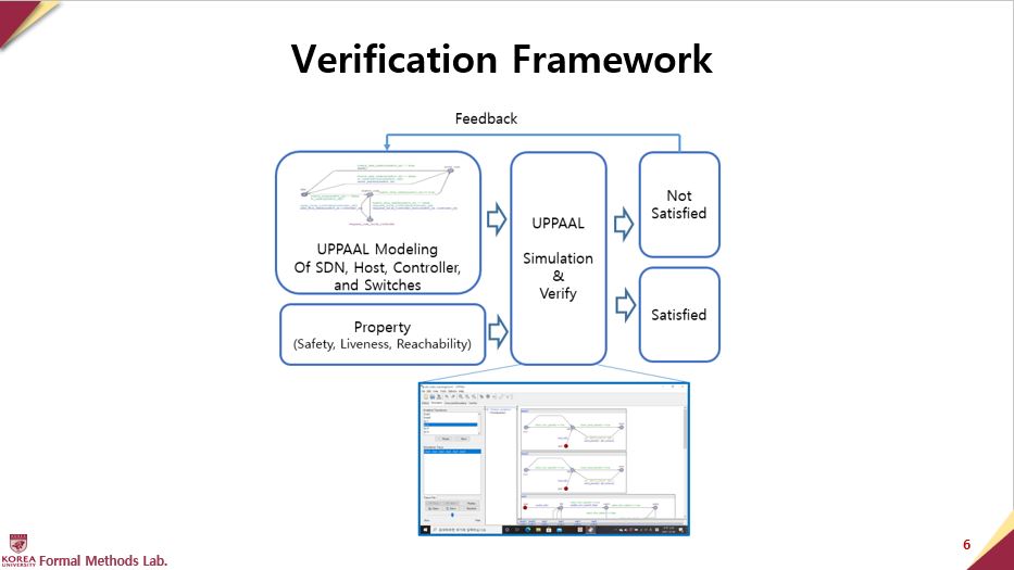 |
The formal framework in Figure consists of controllers, switches, and hosts at UPPAAL modeling. Simulations can be used to confirm that the model operates as intended. In particular, the safety, reachability, and liveness at Properties of the system can be verified. As a result of this verification process, users receive either a Satisfied or Not Satisfied message. In the framework, the model and its properties are modified through feedback, and then verification is run again.
As an application of the framework, the topology is modeled with SDN components, including the hosts, controller, and switches. Furthermore, the network configuration can be changed through the alternation of the topology, depending on various network conditions such as node failure, QoS requirements, and cost reduction. Each SDN is modeled with two different topologies. The forwarding rule must be applied well, even though the network changes to a different topology. The verification properties are examined for each topology in terms of safety, liveness, and reachability. The maintenance of the forwarding rule is confirmed by verifying the same properties in different topologies. The results of “Not Satisfied” or “Satisfied” are displayed after the properties are input to UPPAAL Verify, the middle part of Figure 2. It can be confirmed that the same forwarding rule is applied if Satisfied is obtained as a result after two SDNs with different topologies are modeled and verified for the same property.
|
|
ICACT20220362 Slide.05
[Big slide for presentation]
[YouTube] |
Chrome Text-to-Speach Click!! |
 |
Formal Framework
&
Modeling
|
|
ICACT20220362 Slide.04
[Big slide for presentation]
[YouTube] |
Chrome Text-to-Speach Click!! |
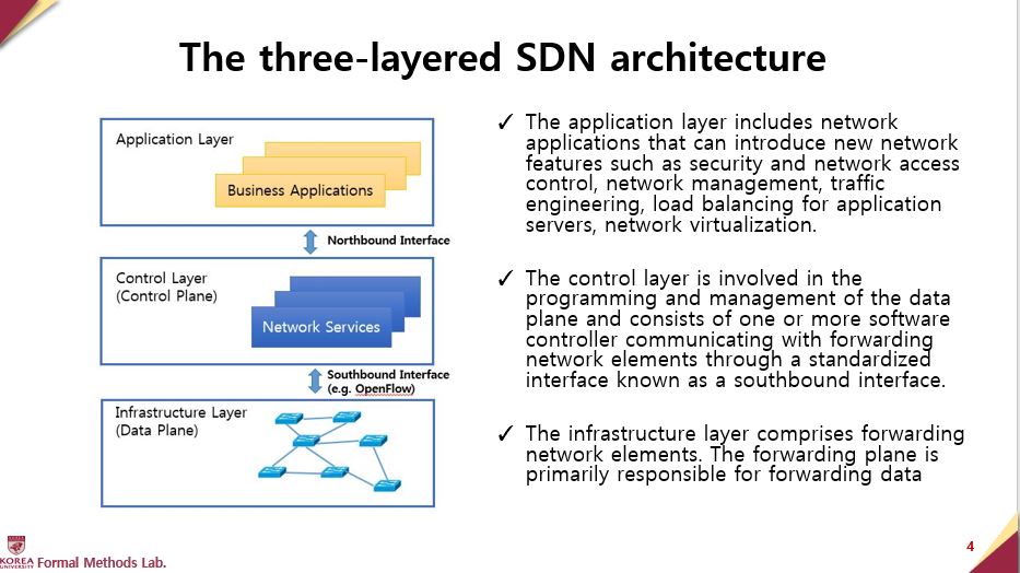 |
This picture shows the SDN framework, which consists of three layers: the application layer, the control layer, and Infrastructure layer.
The application layer includes network applications that can introduce new network features such as security and manageability, provide forwarding schemes, or assist the control layer in the network configuration. The application layer can provide appropriate guidance for the control layer by obtaining an abstracted global view of the network management and traffic engineering, load balancing for application servers, load balancing for application servers, security and network access control, network testing, debugging and verification, inter-domain routing, and network virtualization. The interface between the application layer and the control layer is known as the northbound interface.
In the lower layer, the control plane is found. This is involved in the programming and management of the forwarding plane. In order to achieve this, it uses information provided by the forwarding plane. In order to achieve this, it uses information provided by the forwarding plane and defines network operations and routing. It consists through a standardized interface known as a southbound interface. OpenFlow, one of the most commonly used southbound interfaces, primarily considers switch
|
|
ICACT20220362 Slide.03
[Big slide for presentation]
[YouTube] |
Chrome Text-to-Speach Click!! |
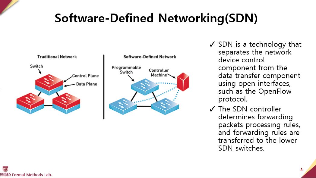 |
SDN is a technology that separates the network device control component from the data transfer component using open interfaces, such as the OpenFlow protocol.
The SDN controller determines forwarding packets processing rules, and forwarding rules are transferred to the lower SDN switches
|
|
ICACT20220362 Slide.02
[Big slide for presentation]
[YouTube] |
Chrome Text-to-Speach Click!! |
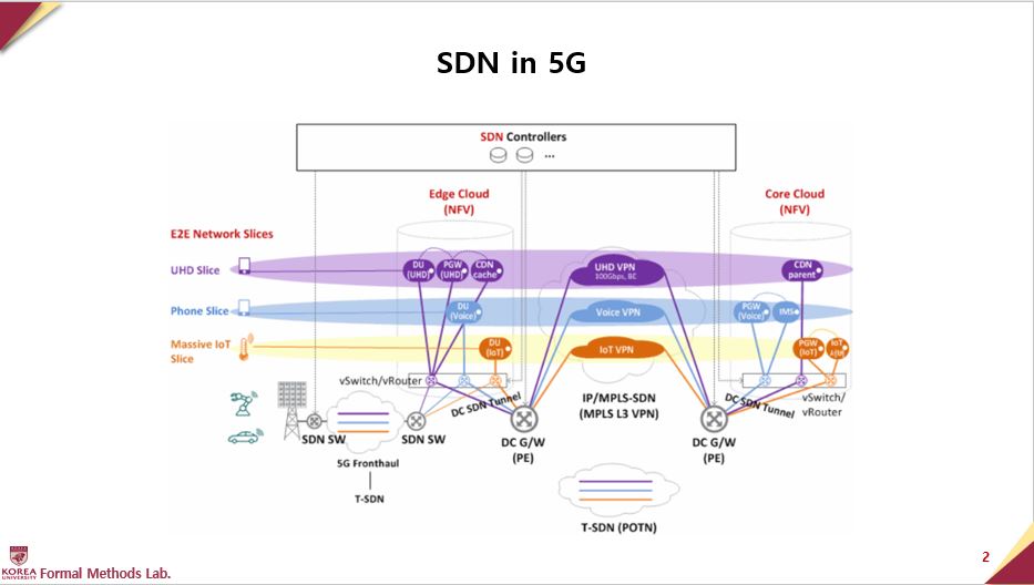 |
Before I start to share research, I would like to introduce what is Software-Defined Networking, SDN
which is now used as the core technology for 5G networks. This provides many advantages over traditional networking by separating the controller and data planes. However, the network topology changes depend on the network configuration frequency. Therefore, it requires applying consistent network rules and providing network resilience. In this paper, provide a verification framework based on the model checking, and to ensure resilience, verify both a topology and modified topology with formal verification.
|
|
ICACT20220362 Slide.01
[Big slide for presentation]
[YouTube] |
Chrome Text-to-Speach Click!! |
 |
Hi everybody, my name is Miyoung Kang. Our presentation today is about Modeling and Verification for SDN, that we called Verification Framework for Software-Defined Networking
|