 ICACT20210139 Slide.15
[Big slide for presentation] |
Chrome Text-to-Speach Click!! |
 |
Thank You
|
|
ICACT20210139 Slide.14
[Big slide for presentation]
|
Chrome Text-to-Speach Click!! |
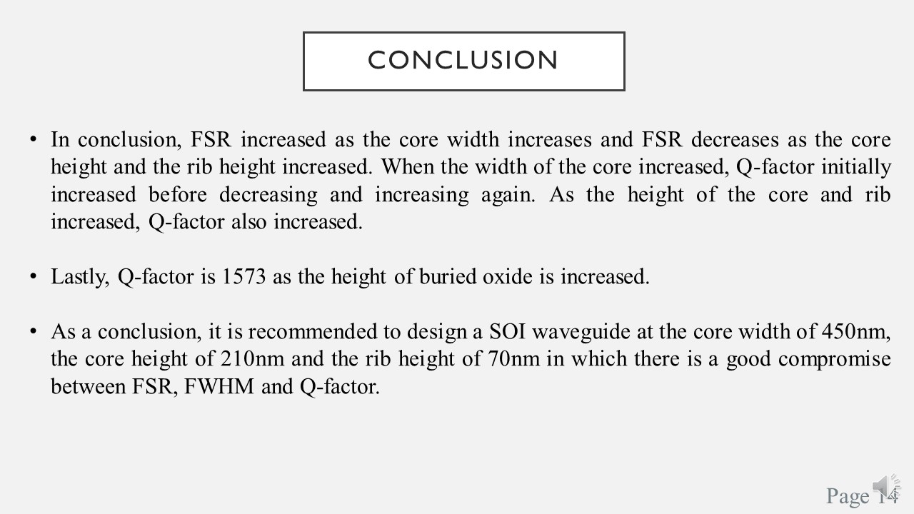 |
In conclusion, it is seen that FSR increased as the core width increases and FSR decreases as the core height and the rib height increased.
When the width of the core increased, Q-factor initially increased before decreasing and increasing again.
As the height of the core and rib increased, Q-factor also increased.
Lastly, Q-factor is 1573 as the height of buried oxide is increased. As a conclusion, it is recommended to design a SOI waveguide at the core width of 450nm, the core height of 210nm and the rib height of 70nm in which there is a good compromise between FSR, FWHM and Q-factor.
|
|
ICACT20210139 Slide.13
[Big slide for presentation]
|
Chrome Text-to-Speach Click!! |
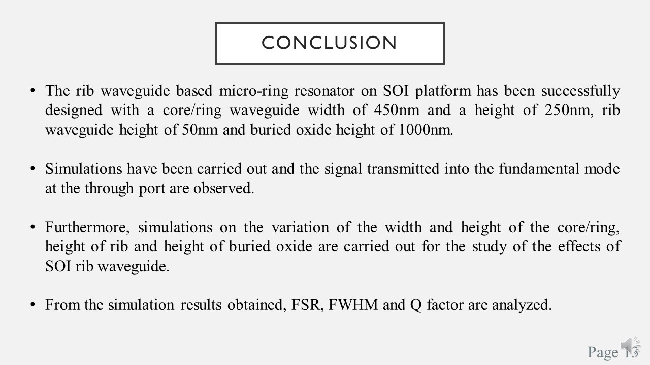 |
Conclusion.
The rib waveguide based micro-ring resonator on SOI platform has been successfully designed with a core/ring waveguide width of 450nm and a height of 250nm, rib waveguide height of 50nm and buried oxide height of 1000nm.
Simulations have been carried out and the signal transmitted into the fundamental mode at the through port are observed.
Furthermore, simulations on the variation of the width and height of the core/ring, height of rib and height of buried oxide are carried out for the study of the effects of SOI rib waveguide.
From the simulation results obtained, FSR, FWHM and Q factor are analyzed.
|
|
ICACT20210139 Slide.12
[Big slide for presentation]
|
Chrome Text-to-Speach Click!! |
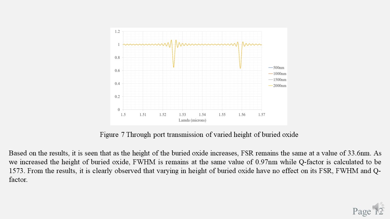 |
Lastly, through port transmission of varied height of buried oxide. Based on the results, it is seen that as the height of the buried oxide increases, FSR remains the same at a value of 33.6nm.
As we increased the height of buried oxide, FWHM is remains at the same value of 0.97nm while Q-factor is calculated to be 1573.
From the results, it is clearly observed that varying in height of buried oxide have no effect on its FSR, FWHM and Q-factor.
|
|
ICACT20210139 Slide.11
[Big slide for presentation]
|
Chrome Text-to-Speach Click!! |
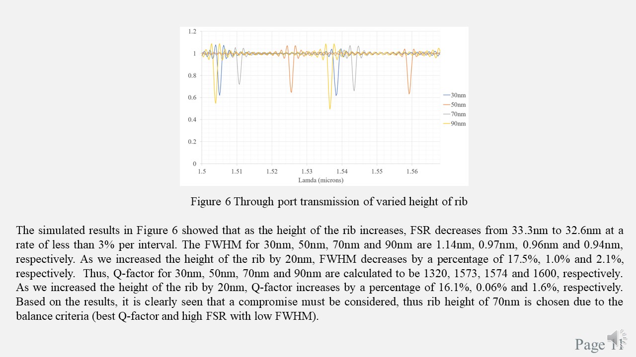 |
While for varied rib height, it is seen that as the rib height increases, FSR and FWHM will be also decreases.
Whereas, for Q-factor, as we increased the rib height, Q-factor increased.
Thus, based on the results findings, it is clearly seen that a compromise must be considered, thus rib height of 70nm is chosen due to the balance criteria (in here, we want best Q-factor and high FSR with low FWHM).
|
|
ICACT20210139 Slide.10
[Big slide for presentation]
|
Chrome Text-to-Speach Click!! |
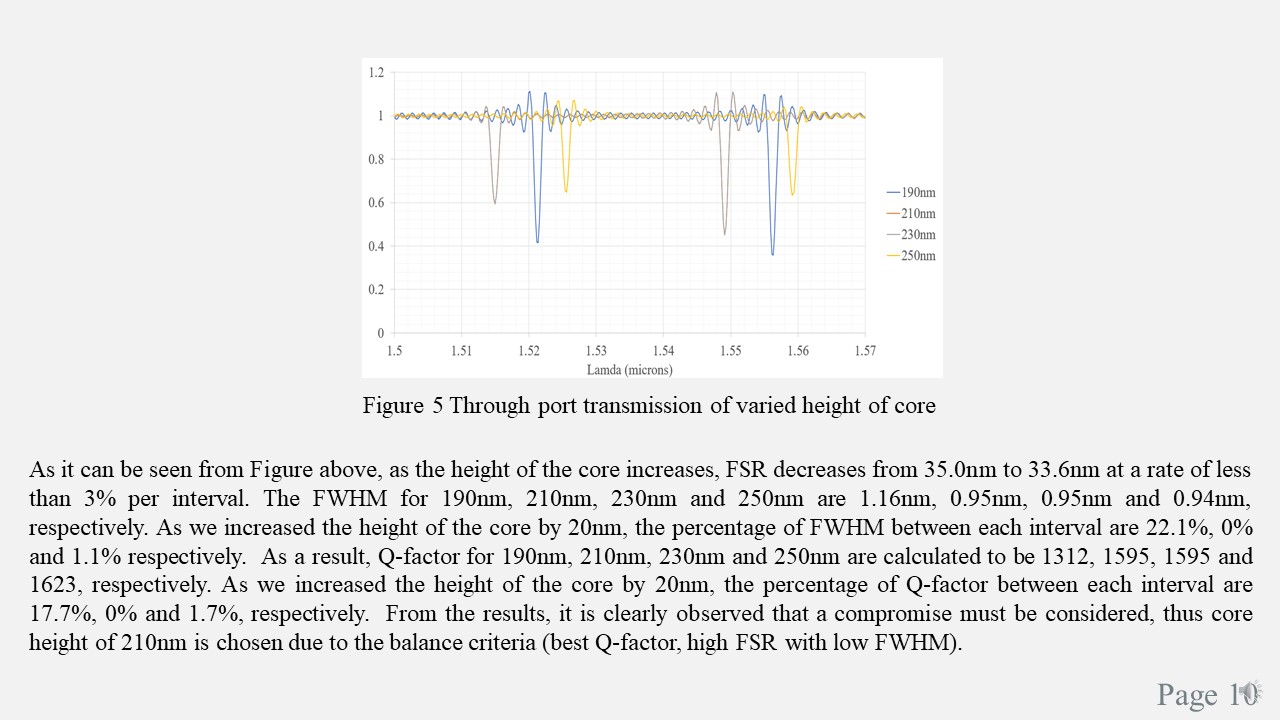 |
Next, through port transmission of varied core height. As it can be seen from Figure above, it is seen that as the core height increases, FSR and FWHM will be decreases.
Whereas Q-factor increases as we increased the core height.
From the results, it is clearly observed that a good compromise must be considered, thus core height of 210nm is chosen due to the balance criteria (best Q-factor, high FSR with low FWHM).
|
|
ICACT20210139 Slide.09
[Big slide for presentation]
|
Chrome Text-to-Speach Click!! |
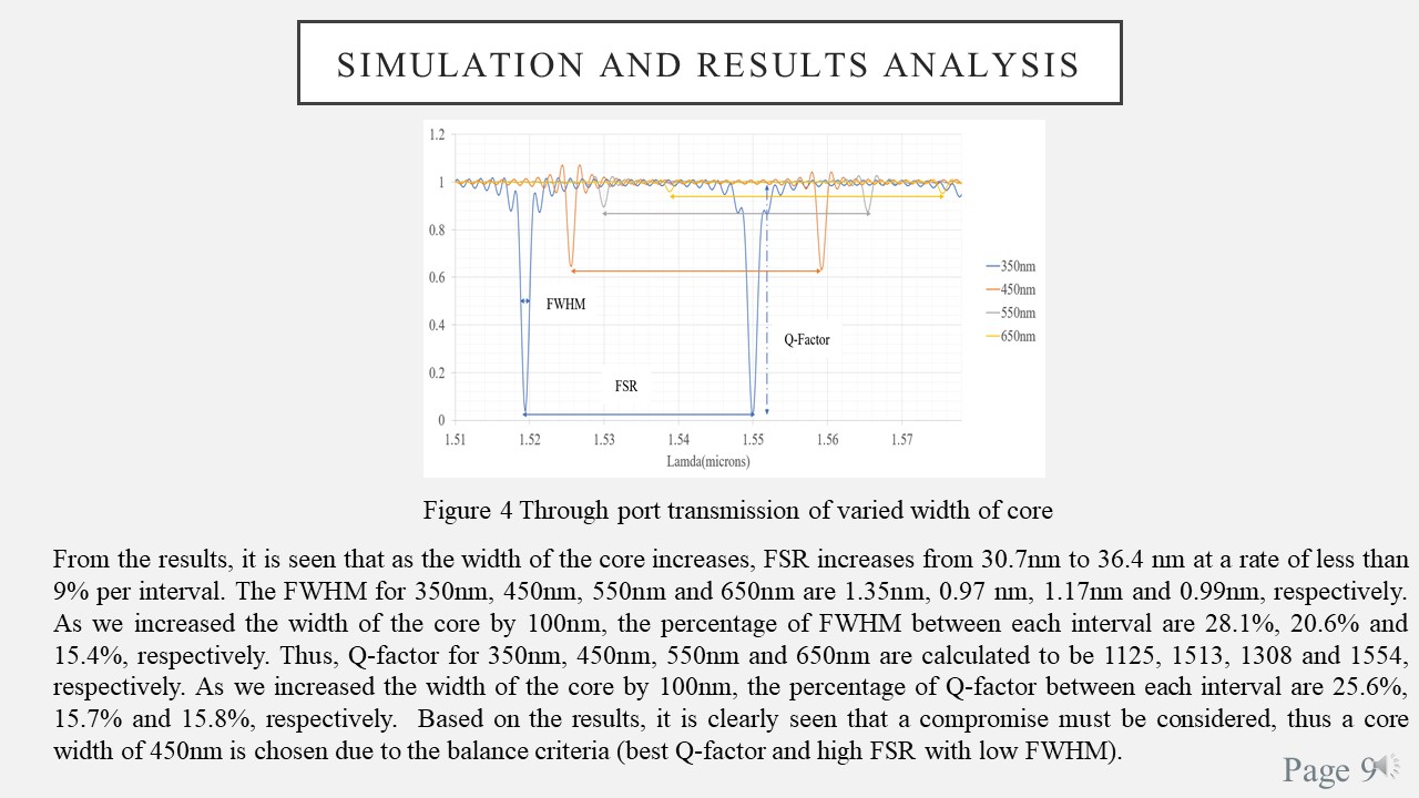 |
The proposed design from previous slide is simulated and the results obtained is shown in Figure 4.
Figure 4 shows the through port transmission of varied core width. From the results, it is seen that as we increased the core width, FSR increases from 30.7nm to 36.4 nm at a rate of less than 9% per interval.
The FWHM for 350nm, 450nm, 550nm and 650nm are 1.35nm, 0.97 nm, 1.17nm and 0.99nm, respectively.
As we increased the core width by 100nm, the percentage of FWHM between each interval are 28.1%, 20.6% and 15.4%, respectively. Thus, Q-factor for 350nm, 450nm, 550nm and 650nm are calculated to be 1125, 1513, 1308 and lastly 1554, respectively.
As we increased the core width by 100nm, the percentage of Q-factor between each interval are 25.6%, 15.7% and 15.8%, respectively. So, based on the results, it is clearly seen that a compromise must be considered, thus a core width of 450nm is chosen due to the balance criteria (best Q-factor and high FSR with low FWHM).
|
|
ICACT20210139 Slide.08
[Big slide for presentation]
|
Chrome Text-to-Speach Click!! |
 |
Subsequently, the width of the core/ring will be varied from 350nm to 650nm at an interval of 100nm, whereas the height of the core/ring will be varied from 190nm to 250nm at the interval of 30nm, the height of rib is varied from 30nm to 90nm at the interval of 20nm and the height of the buried oxide is varied from 500nm to 2000nm at the interval of 500nm.
Each of the dimensions will be varied at distinct value with a specific interval and only the results of through port are plotted into graphs.
Free spectral (FSR), FWHM and Q factor are key performance metrics for this silicon on insulator (SOI) based waveguide design.
To achieve a good performance of MRR, the MRR must exhibit the characteristics of wide FSR, low FWHM and high Q-factor.
The value of wavelength resonance used for calculation of Q factor is dependent on the wavelength selected.
|
|
ICACT20210139 Slide.07
[Big slide for presentation]
|
Chrome Text-to-Speach Click!! |
 |
Next, the Design of Rib Waveguide based Micro-Ring Resonator.
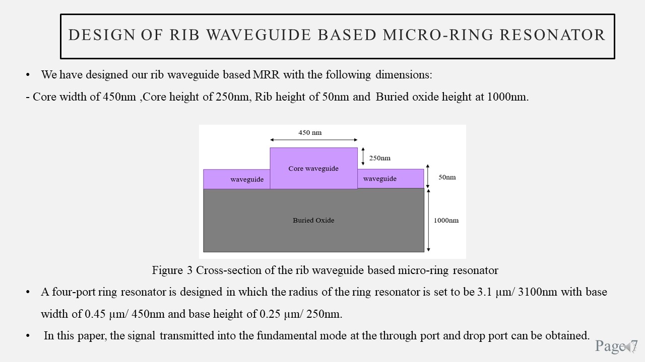
We have designed our rib waveguide based MRR with the following dimensions: Core width of 450nm, Core height of 250nm, Rib height of 50nm and Buried oxide height at 1000nm.
Cross-section of the rib waveguide based micro-ring resonator is shown in Figure 3.
A four-port ring resonator is designed in which the radius of the ring resonator is set to be 3.1 µm/ 3100nm with base width of 450nm and base height of 250nm.
In this paper, the signal transmitted into the fundamental mode at the through port and drop port can be obtained.
|
|
ICACT20210139 Slide.06
[Big slide for presentation]
|
Chrome Text-to-Speach Click!! |
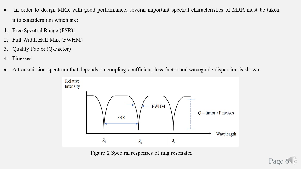 |
In order to design MRR with good performance, several important spectral characteristics of MRR must be taken into consideration which are; Free Spectral Range: It can be calculated by the difference between two successive peaks of resonance.
And next, Full Width Half Max: It is defined as the full width at half maximum of one peak.
And Quality Factor: It is defined as the ratio of resonant wavelength to FWHM.
And lastly, Finesses: It is defined as the ratio of FSR to FWHM.
|
|
ICACT20210139 Slide.05
[Big slide for presentation]
|
Chrome Text-to-Speach Click!! |
 |
Now, lets us look at the Background study on Micro-Ring Resonator (MRR) and its Spectral Characteristics.
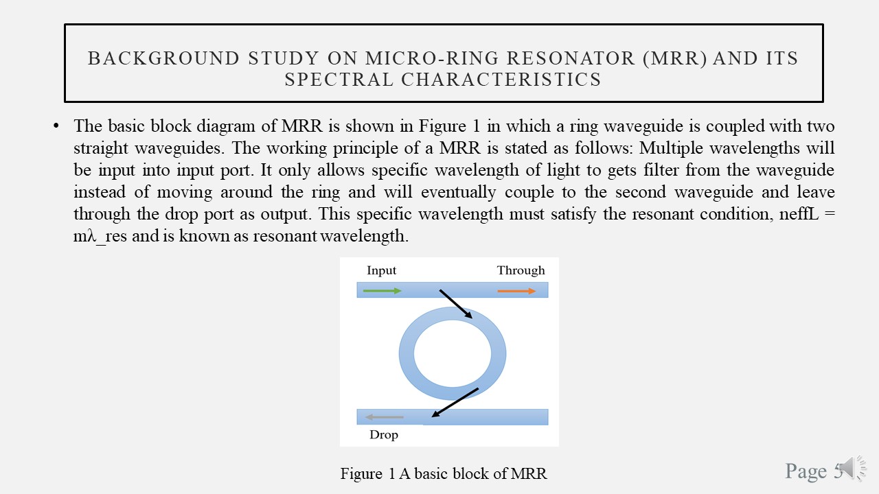
The basic block diagram of MRR is shown in Figure 1 in which a ring waveguide is coupled with two straight waveguides.
The working principle of a MRR is stated as follows: Multiple wavelengths will be input into input port.
It only allows specific wavelength of light to gets filter from the waveguide instead of moving around the ring and will eventually couple to the second waveguide and leave through the drop port as output.
This specific wavelength must satisfy the resonant condition, neffL = mλ_res and is known as resonant wavelength.
|
|
ICACT20210139 Slide.04
[Big slide for presentation]
|
Chrome Text-to-Speach Click!! |
 |
The objective of my work to demonstrate the simulation and analysis of the effects of SOI rib waveguide based on MRR with various dimensions which included the width and height of the core/ring, height of rib and height of buried oxide.
|
|
ICACT20210139 Slide.03
[Big slide for presentation]
|
Chrome Text-to-Speach Click!! |
 |
In recent past, silicon photonics has been one of the most fascinating topics in communication world’s in which tremendous impacts have been realized by utilizing Silicon-On-Insulator (SOI) platform with very thin top layer of silicon.
SOI platform are often recognized on behalf of its high index contrast and compatibility with Complementary Metal-Oxide-Semiconductor (CMOS) technology.
The most standard design of single mode SOI nanowire commonly have a cross section of approximately 500nm x 220nm.Optical waveguide such as SOI based platform waveguide is acknowledged as the most extensive bridging element in optical integrated devices.
Therefore upon, a low loss optical waveguide is important in the design and fabrication of reliable and effective optical communication system.
Low loss optical waveguides can be attained by applying or varying various parameters.
With low loss optical waveguide structure, low processing cost can be achieved with low-cost device during fabrication process.
Among these types of optical filters, MRR based structure is recognize as superior as a result of high Q-factor, high transmission at resonance and high extinction ratio.
|
|
ICACT20210139 Slide.02
[Big slide for presentation]
|
Chrome Text-to-Speach Click!! |
 |
Today I will be discussing on the introduction, objective, background study on MRR and its spectral characteristics, design of rib waveguide based MRR, simulation and result analysis and lastly the conclusion.
|
|
ICACT20210139 Slide.01
[Big slide for presentation]
|
Chrome Text-to-Speach Click!! |
 |
Good morning, my name is Angie Teo and I am from Brunei Darussalam. Today I will be presenting a topic name SOI Rib Waveguide Physical Dimension Dependent Micro Ring Resonator Characterization.
|
















