 ICACT20230060 Slide.29
[Big slide for presentation]
[YouTube] |
Chrome Text-to-Speach Click!! |
 |
Any question if you have, please ask me.
|
|
ICACT20230060 Slide.28
[Big slide for presentation]
[YouTube] |
Chrome Text-to-Speach Click!! |
 |
Future Work
Based on MSB-SE analysis of motor current and voltage signals of different severity and sensor less control (closed) mode.
In addition, more advanced signal processing technology and sensor less driver are used to extract weak fault signals from noise polluted current and voltage measurements.
Provide information and guidance for any possible future research in this field.
|
|
ICACT20230060 Slide.27
[Big slide for presentation]
[YouTube] |
Chrome Text-to-Speach Click!! |
 |
Paper Summary:
This study defines the load torque demand, which is the torque required to drive the load at a given speed.
The load torque demand is proportional to the square of the speed. This is typical for gear systems.
The information provided defines the motor torque capability as a function of speed.
The steady-state running speed and torque of the motor driving the load are the intersection of the motor torque capacity curve and the load torque demand curve.
If the actual operating speed is higher or lower than the normal operating point when the induction motor is initially energized, the excess motor torque capability is applied to accelerate the gear system and load inertia to the normal operating speed.
|
|
ICACT20230060 Slide.26
[Big slide for presentation]
[YouTube] |
Chrome Text-to-Speach Click!! |
 |
Paper Summary And Future Work.
|
|
ICACT20230060 Slide.25
[Big slide for presentation]
[YouTube] |
Chrome Text-to-Speach Click!! |
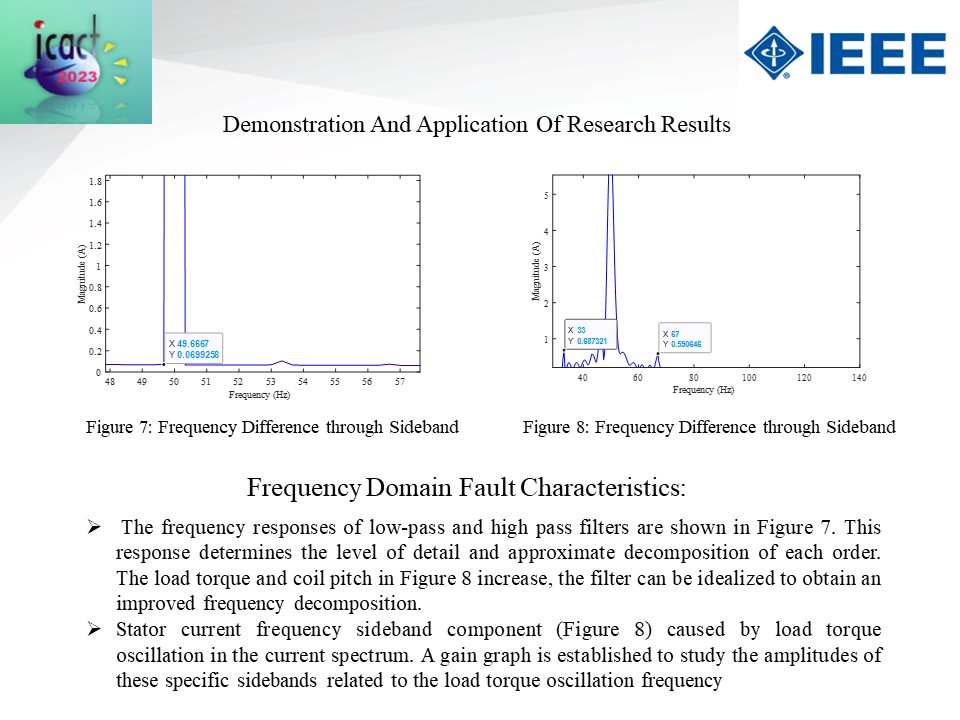 |
Frequency Domain Fault Characteristics:
The frequency responses of low-pass and high pass filters are shown in Figure 7. This response determines the level of detail and approximate decomposition of each order. The load torque and coil pitch in Figure 8 increase, the filter can be idealized to obtain an improved frequency decomposition.
Stator current frequency sideband component (Figure 8) caused by load torque oscillation in the current spectrum. A gain graph is established to study the amplitudes of these specific sidebands related to the load torque oscillation frequency
|
|
ICACT20230060 Slide.24
[Big slide for presentation]
[YouTube] |
Chrome Text-to-Speach Click!! |
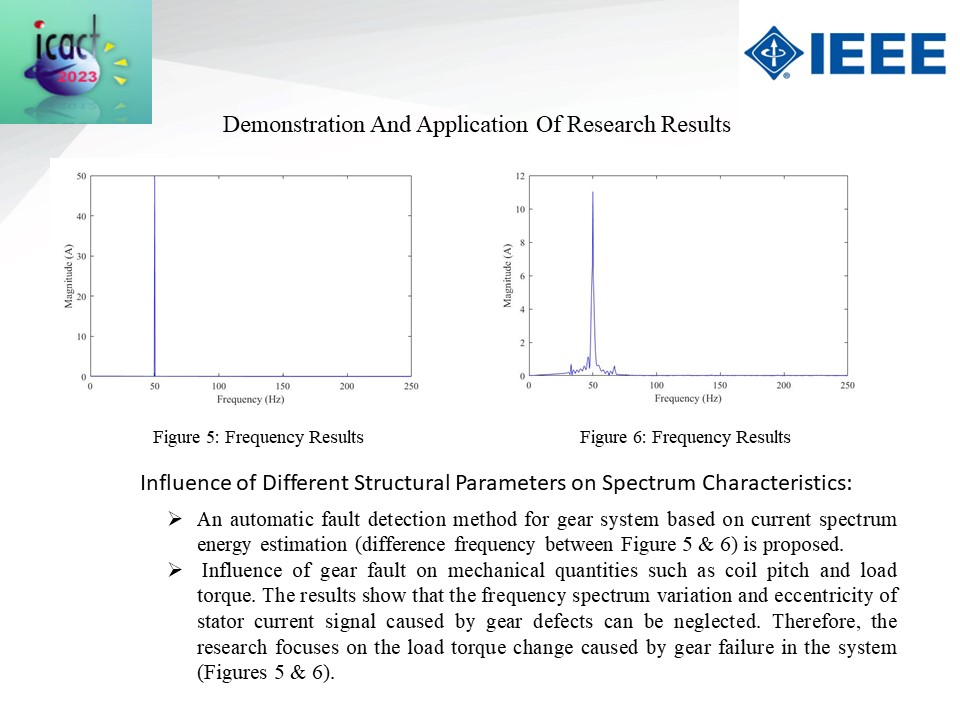 |
Influence of Different Structural Parameters on Spectrum Characteristics:
An automatic fault detection method for gear system based on current spectrum energy estimation (difference frequency between Figure 5 & 6) is proposed.
Influence of gear fault on mechanical quantities such as coil pitch and load torque. The results show that the frequency spectrum variation and eccentricity of stator current signal caused by gear defects can be neglected. Therefore, the research focuses on the load torque change caused by gear failure in the system (Figures 5 & 6).
|
|
ICACT20230060 Slide.23
[Big slide for presentation]
[YouTube] |
Chrome Text-to-Speach Click!! |
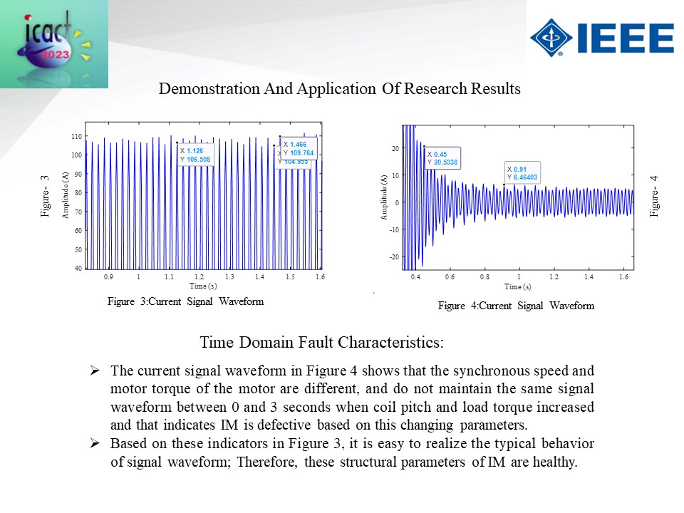 |
Time Domain Fault Characteristics:
The current signal waveform in Figure 4 shows that the synchronous speed and motor torque of the motor are different, and do not maintain the same signal waveform between 0 and 3 seconds when coil pitch and load torque increased and that indicates IM is defective based on this changing parameter.
Based on these indicators in Figure 3, it is easy to realize the typical behavior of signal waveform; Therefore, these structural parameters of IM are healthy.
|
|
ICACT20230060 Slide.22
[Big slide for presentation]
[YouTube] |
Chrome Text-to-Speach Click!! |
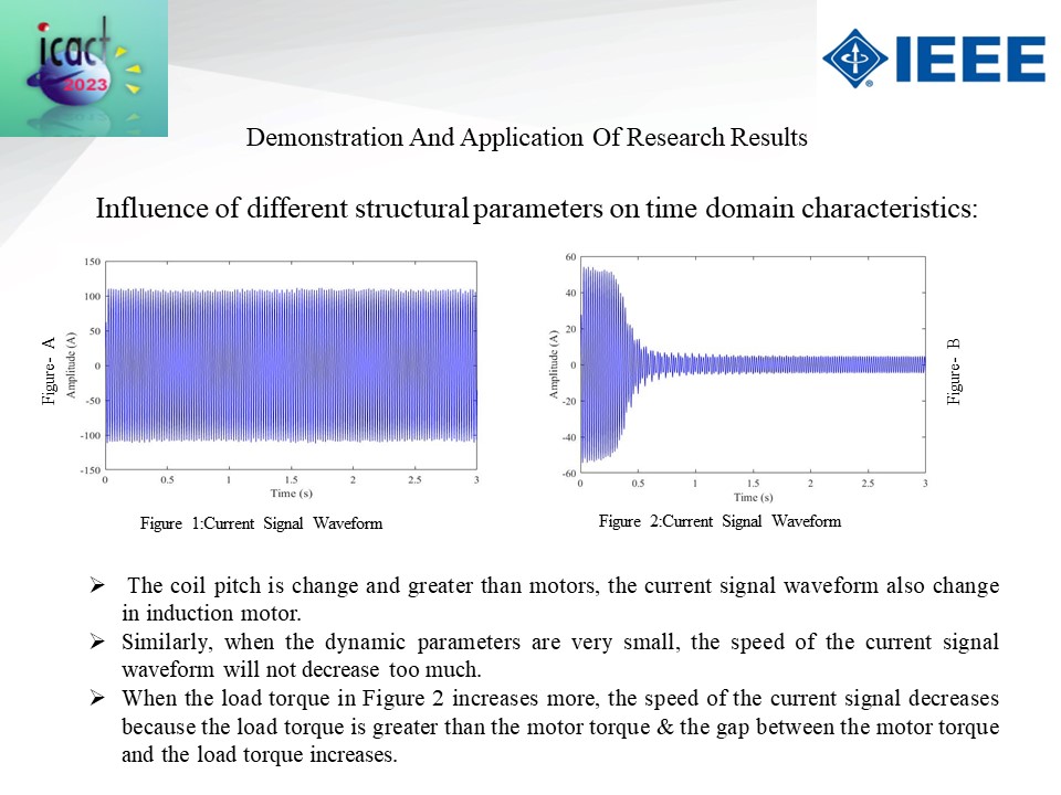 |
Influence of different structural parameters on time domain characteristics:
The coil pitch is change and greater than motors, the current signal waveform also change in induction motor.
Similarly, when the dynamic parameters are very small, the speed of the current signal waveform will not decrease too much.
When the load torque in Figure 2 increases more, the speed of the current signal decreases because the load torque is greater than the motor torque & the gap between the motor torque and the load torque increases
|
|
ICACT20230060 Slide.21
[Big slide for presentation]
[YouTube] |
Chrome Text-to-Speach Click!! |
 |
Demonstration And Application of Research Results
|
|
ICACT20230060 Slide.20
[Big slide for presentation]
[YouTube] |
Chrome Text-to-Speach Click!! |
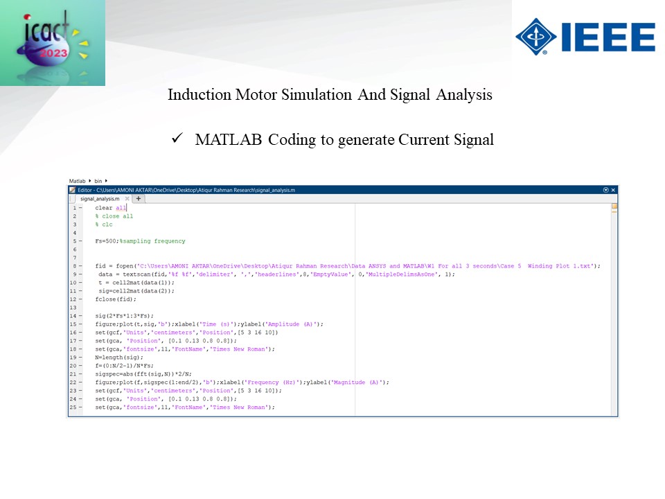 |
Then do the MATLAB coding to get the signal result and graph.
|
|
ICACT20230060 Slide.19
[Big slide for presentation]
[YouTube] |
Chrome Text-to-Speach Click!! |
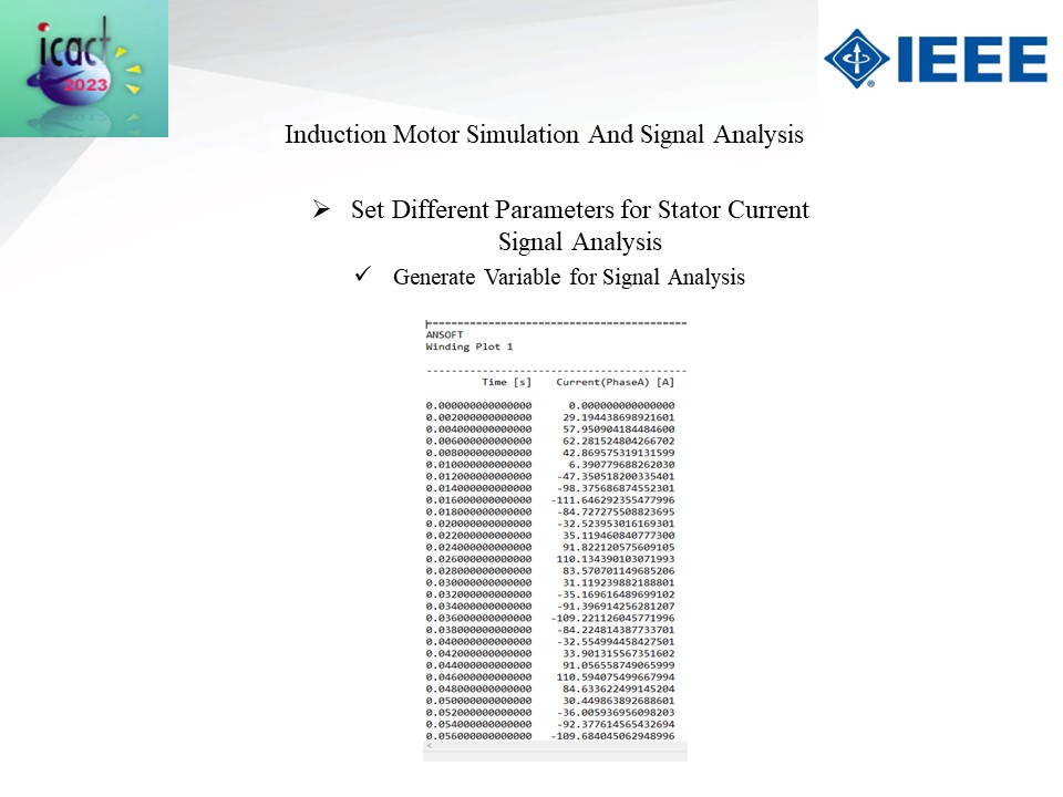 |
From result generate the variables for signal analysis.
|
|
ICACT20230060 Slide.18
[Big slide for presentation]
[YouTube] |
Chrome Text-to-Speach Click!! |
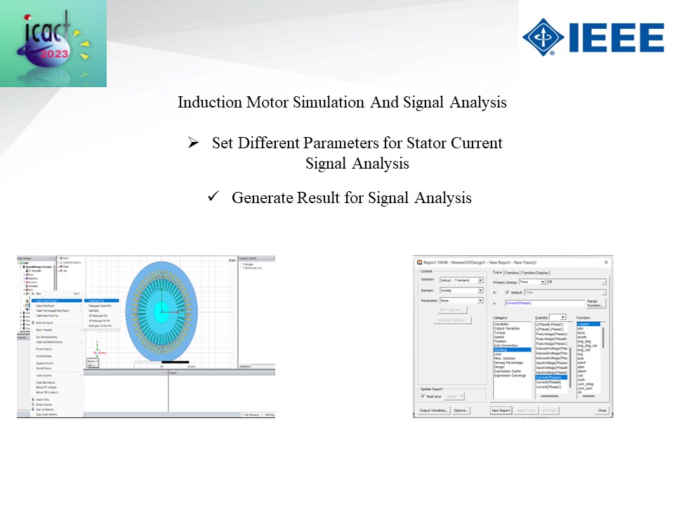 |
The generate the result for signal analysis
|
|
ICACT20230060 Slide.17
[Big slide for presentation]
[YouTube] |
Chrome Text-to-Speach Click!! |
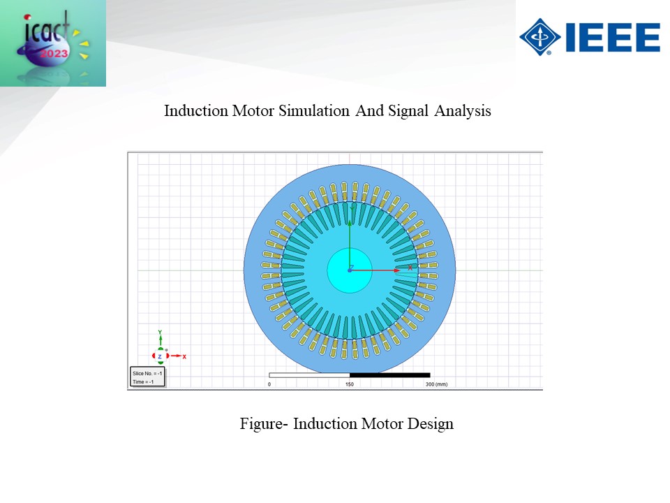 |
This is the figure of IM.
|
|
ICACT20230060 Slide.16
[Big slide for presentation]
[YouTube] |
Chrome Text-to-Speach Click!! |
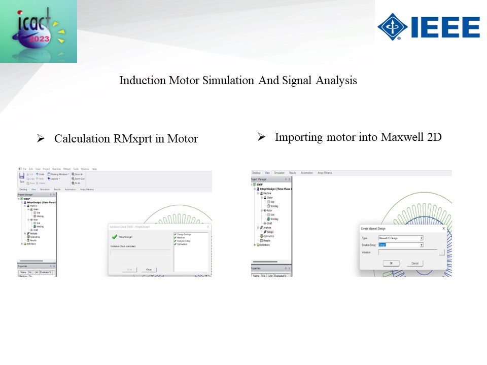 |
Calculate RMxprt for IM validation and then import the motor into maxwell 2D design
|
|
ICACT20230060 Slide.15
[Big slide for presentation]
[YouTube] |
Chrome Text-to-Speach Click!! |
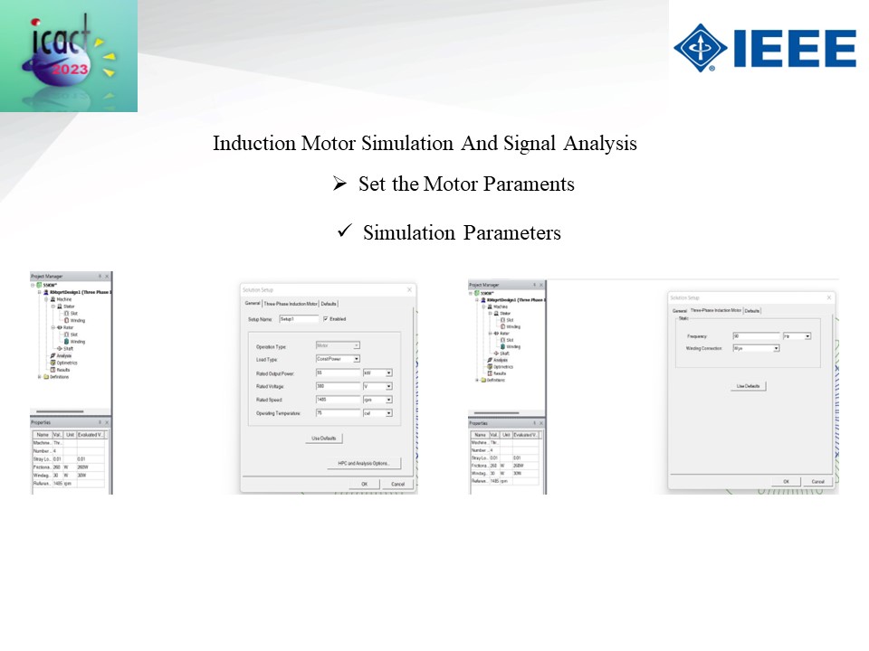 |
Simulate the parameters for IM.
|
|
ICACT20230060 Slide.14
[Big slide for presentation]
[YouTube] |
Chrome Text-to-Speach Click!! |
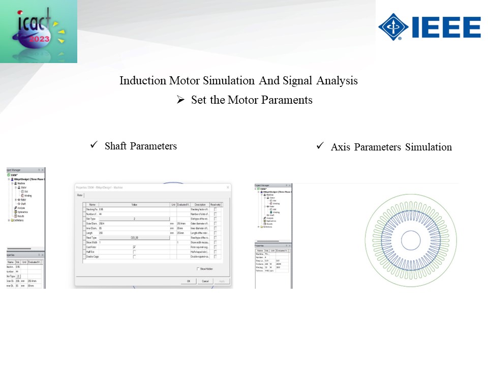 |
Set the shaft and axis parameters simulations
|
|
ICACT20230060 Slide.13
[Big slide for presentation]
[YouTube] |
Chrome Text-to-Speach Click!! |
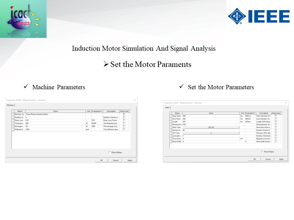 |
Set the machine parameters and motor parameters for 55KV IM simulation.
|
|
ICACT20230060 Slide.12
[Big slide for presentation]
[YouTube] |
Chrome Text-to-Speach Click!! |
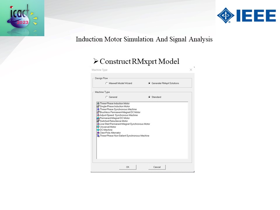 |
Construct the RMxprt design flow and machine type is standard
|
|
ICACT20230060 Slide.11
[Big slide for presentation]
[YouTube] |
Chrome Text-to-Speach Click!! |
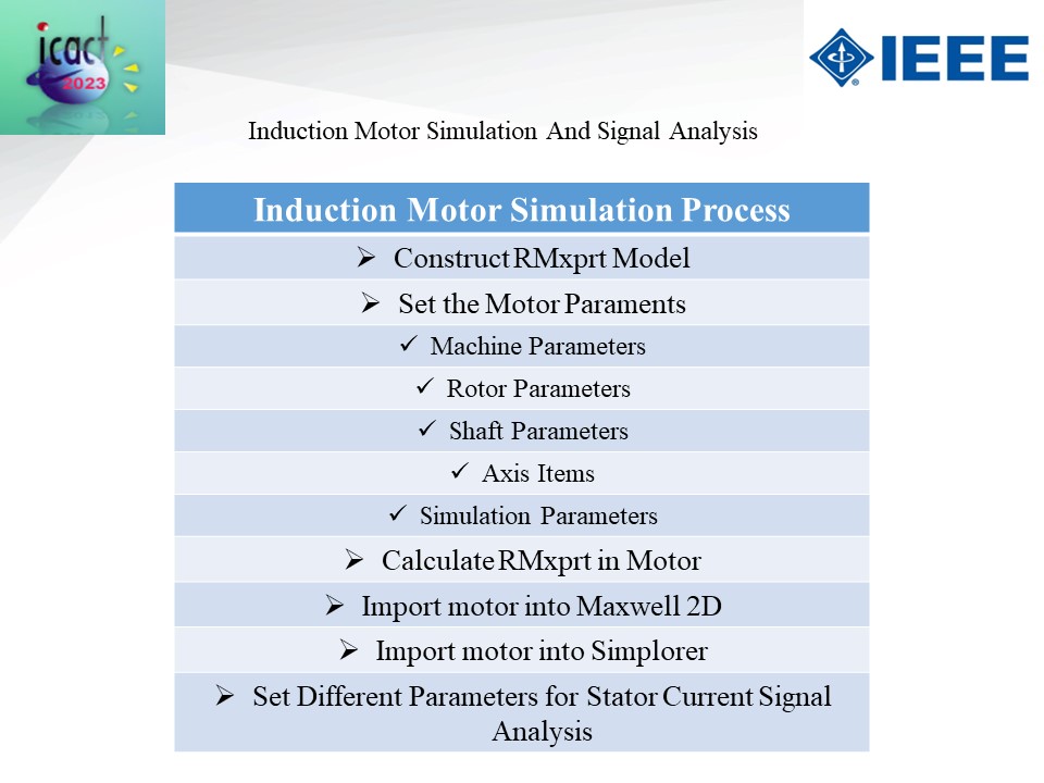 |
To begin the induction motor simulation procedure, we build the RMxprt model and then configure the machine, rotor, shaft, axis, and simulation parameters. Calculate the RMxprt model, then import it into Simplorer and Maxwell 2D. Finally, configure the various parameters for stator current signal analysis.
|
|
ICACT20230060 Slide.10
[Big slide for presentation]
[YouTube] |
Chrome Text-to-Speach Click!! |
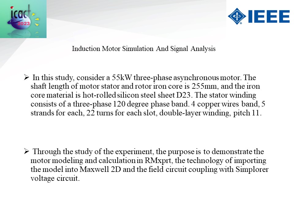 |
For this work we use a 55kW three-phase asynchronous motor. The shaft length of motor stator and rotor iron core is 255mm, and the iron core material is hot-rolled silicon steel sheet D23. The stator winding consists of a three-phase 120-degree phase band. 4 copper wires band, 5 strands for each, 22 turns for each slot, double-layer winding, pitch 11. We did Maxwell 2D model and RMXprt design for calculation.
|
|
ICACT20230060 Slide.09
[Big slide for presentation]
[YouTube] |
Chrome Text-to-Speach Click!! |
 |
We utilize ANSYS for simulation and MATLAB for signal processing graph production.
|
|
ICACT20230060 Slide.08
[Big slide for presentation]
[YouTube] |
Chrome Text-to-Speach Click!! |
 |
Induction Motor Simulation And Signal Analysis
|
|
ICACT20230060 Slide.07
[Big slide for presentation]
[YouTube] |
Chrome Text-to-Speach Click!! |
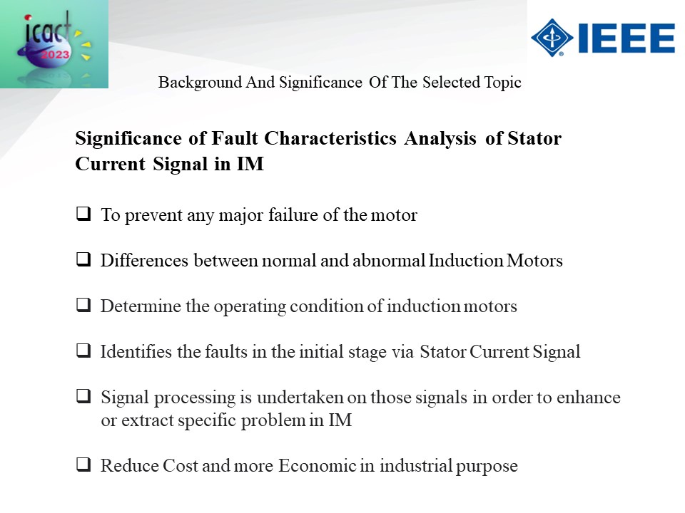 |
We attempt to locate some space where we can have a positive impact on the industrial and scientific fields. We attempt to avoid severe motor failures, distinguish between normal and abnormal IM, operating conditions, signal processing, and decrease the cost of industrial use.
|
|
ICACT20230060 Slide.06
[Big slide for presentation]
[YouTube] |
Chrome Text-to-Speach Click!! |
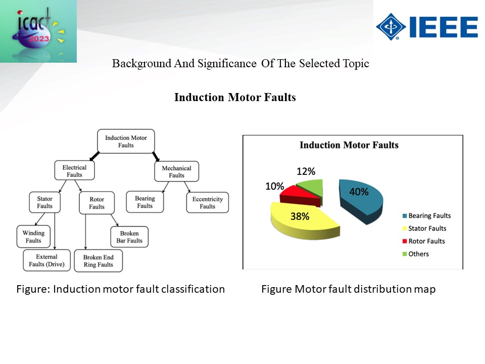 |
Induction motors are divided into two basic systems: electrical faults and mechanical faults. Electrical defects are classified as stator and rotor faults, whereas mechanical flaws are classified as bearing and eccentricity faults. Induction motor bearing fault percentage is 40%, stator fault percentage is 38%, rotor fault percentage is 10%, and others are around 12%.
|
|
ICACT20230060 Slide.05
[Big slide for presentation]
[YouTube] |
Chrome Text-to-Speach Click!! |
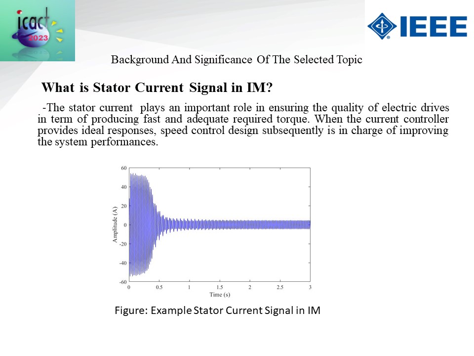 |
We need to understand what the stator current signal is. The stator current is critical in assuring the quality of electric drives in terms of providing the appropriate torque quickly and efficiently. When the current controller produces optimal answers, the speed control design is in charge of enhancing system performance. From that image, we can see how the stator current signal appears in the graph in an abnormal circumstance.
|
|
ICACT20230060 Slide.04
[Big slide for presentation]
[YouTube] |
Chrome Text-to-Speach Click!! |
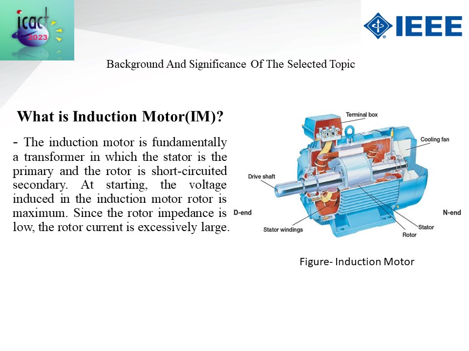 |
First, let me explain the fundamentals of an induction motor. Induction motors are essentially transformers. There is a basic Induction Motor figure. Induction motors are made up of a terminal box, a colling fan, a stator, a rotor, stator windings, and a drive shaft.
|
|
ICACT20230060 Slide.03
[Big slide for presentation]
[YouTube] |
Chrome Text-to-Speach Click!! |
 |
The first issue covered in the lecture is the background and significance of my research study.
|
|
ICACT20230060 Slide.02
[Big slide for presentation]
[YouTube] |
Chrome Text-to-Speach Click!! |
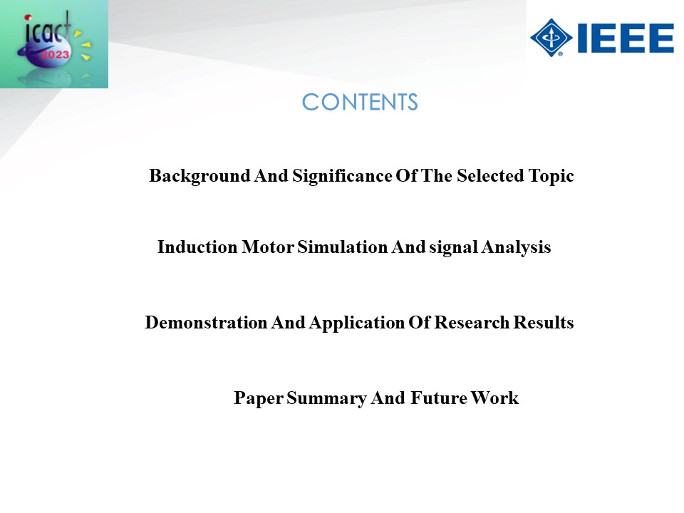 |
Now I'm going to talk about a topic that is linked to my today's presentation. Background and Significance, Induction Motor Simulation and Signal Analysis, Demonstration and Application of Research Results, Paper Summary, and Future Work are the topics covered today presentation.
|
|
ICACT20230060 Slide.01
[Big slide for presentation]
[YouTube] |
Chrome Text-to-Speach Click!! |
 |
Hi everybody, my name is Atiqur Rahman. For ICACT 2023, I have cooperated with one partner from Chittagong Dry Dock Limited, Bangladesh Navy Mr. Azruph Islam Badhon. Our presentation today is about Simulation of Stator Current Signal Fault Characteristics of Induction Motor based on ANSYS.
|
















