 ICACT20210169 Slide.01
[Big Slide]
[YouTube] |
Chrome  Click!! |
 |
Hello, my name is Yoshimi Fujii from Kozo Keikaku Engineering, Japan.
My presentation title is “A 28 GHz Beamforming Technique for 5G Advanced Communication Systems”.
This presentation is about the current status of a part of Japanese government funded research project.
|
| ICACT20210169 Slide.02
[Big Slide]
|
Chrome Click!! |
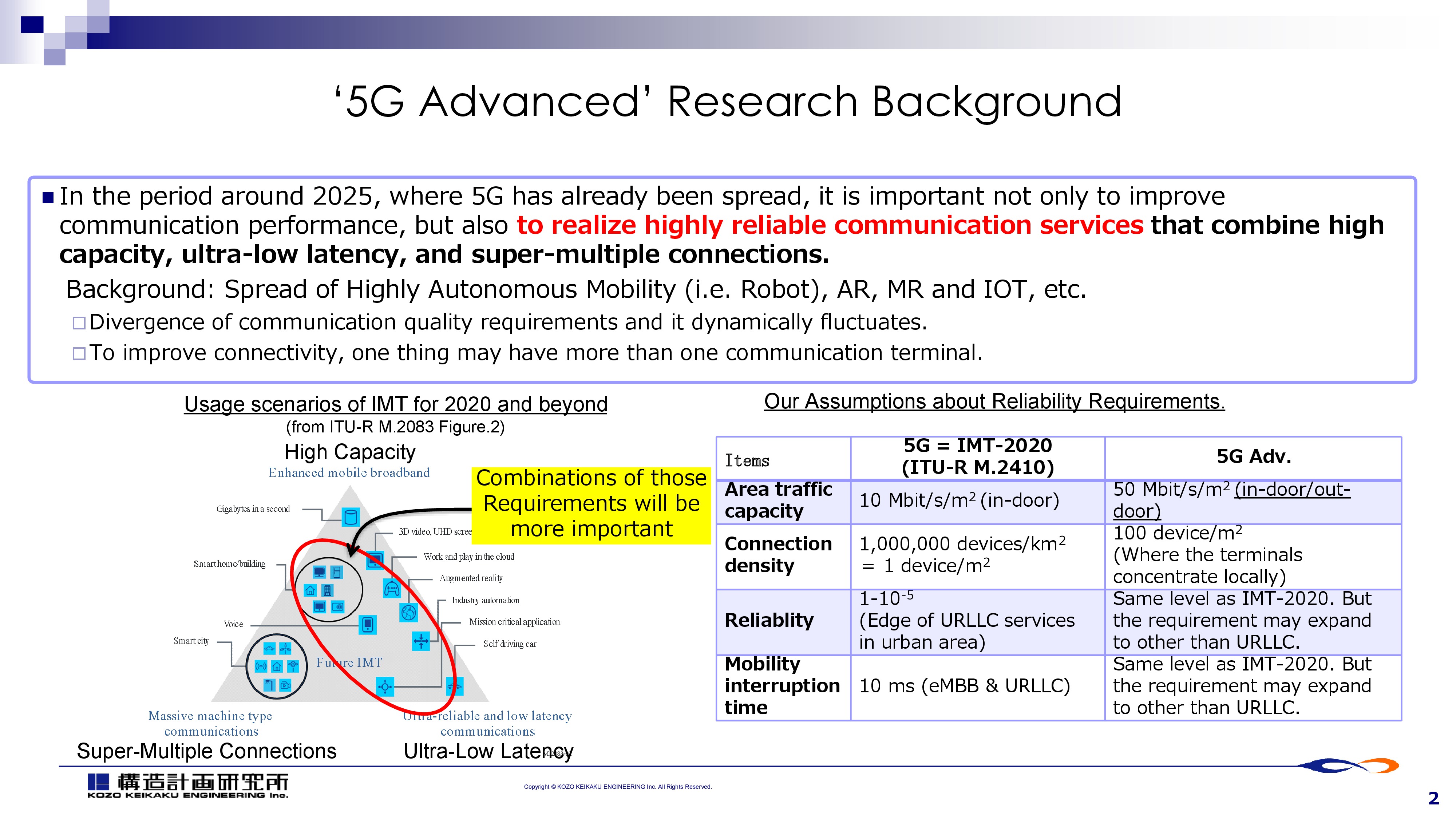 |
Our research project is targeting the wireless technology around 2025, 5-6 years from the original 5G launch.
We call it as ‘5G advanced wireless technology’.
|
| ICACT20210169 Slide.03
[Big Slide]
|
Chrome Click!! |
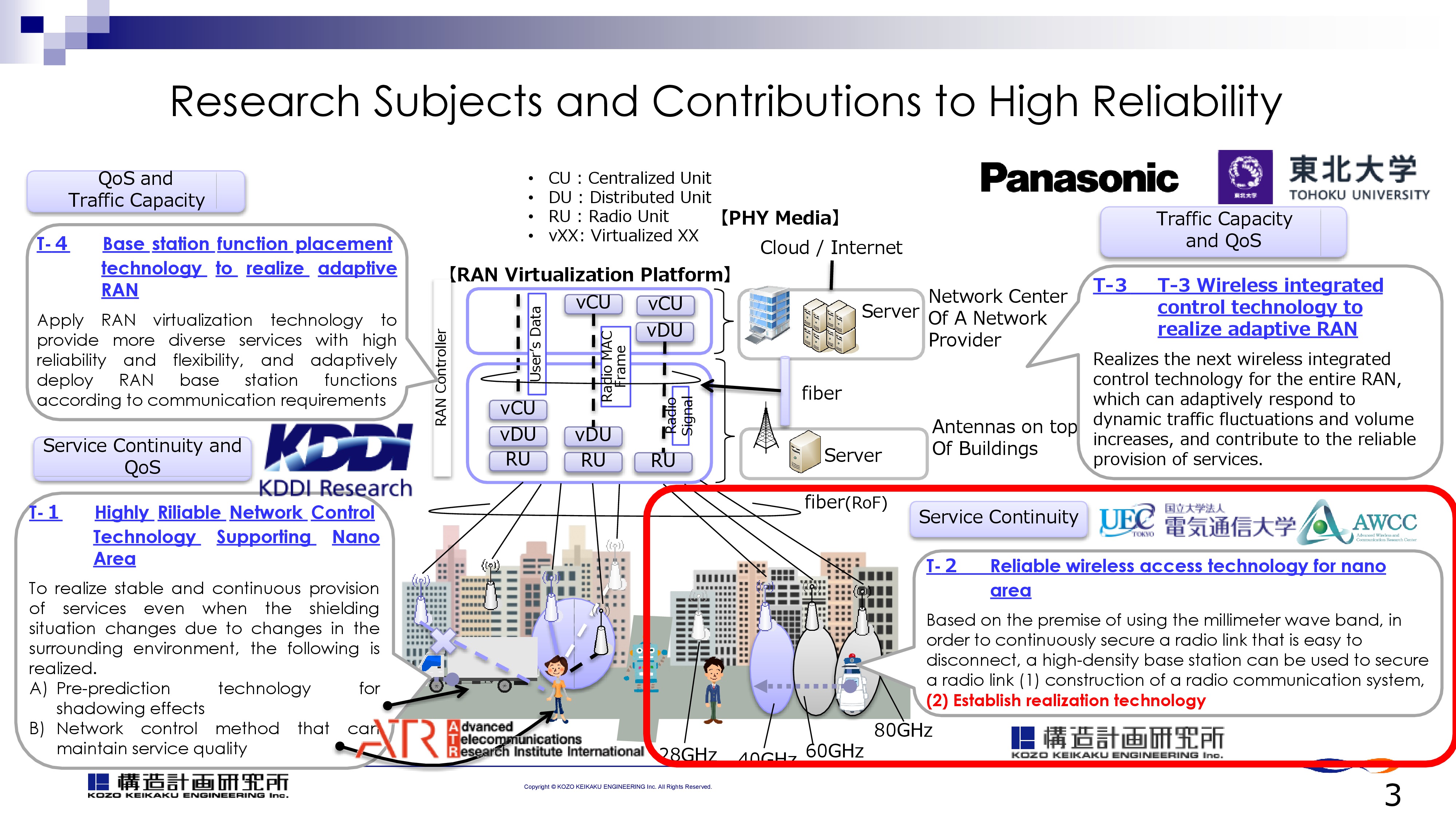 |
This slide shows research project’s organizations and research themes which they are responsible to.
UEC(University of Electro Communications) and KKE are jointly responsible to T-2, “Reliable wireless access technology for nano area”. Here ‘nano-area’ is a small area covered by a set of mmWave base stations.
|
| ICACT20210169 Slide.04
[Big Slide]
|
Chrome Click!! |
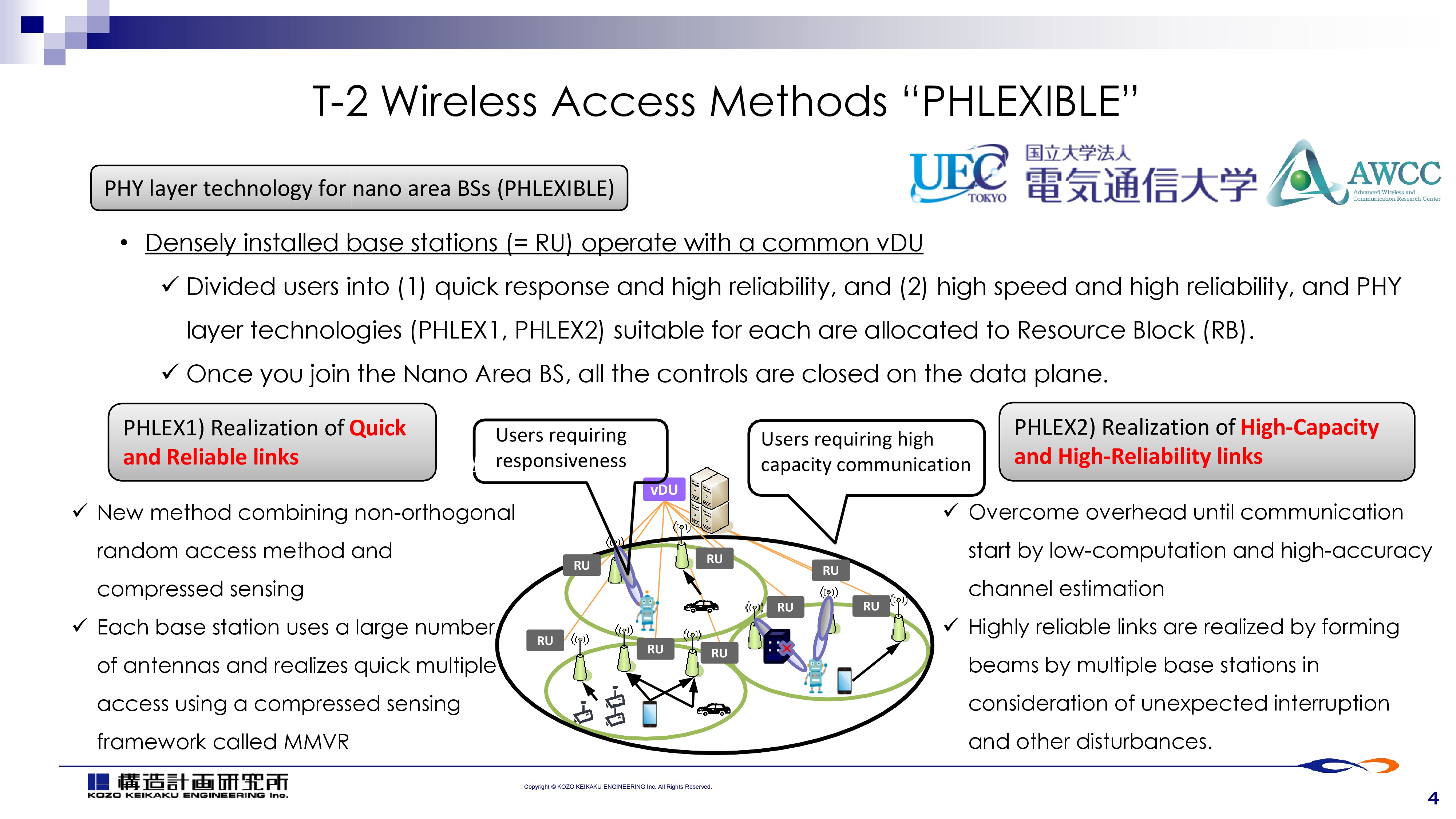 |
Let me introduce our research theme 2, which is enabled by new wireless access methods “PHLEXIBLE”.
We assume there are two different UE groups, have different requirements at the same time.
One group of UEs require Quick and Reliable links, and the other group requires, High-Capacity and High Reliability links.
Those two different groups of UEs exist in the same nano-area, small cell within <100m2 covered by mmWave base stations.
PHLEX1 and PHLEX2 are the access methods designed for the two different requirements.
UEC is responsible to the theoretical aspect of the access methods.
KKE is on the other hand, focusing on the implementation technology.
We assume all the mmWave RUs (Radio Units) are controlled by one vDU. |
| ICACT20210169 Slide.05
[Big Slide]
|
Chrome Click!! |
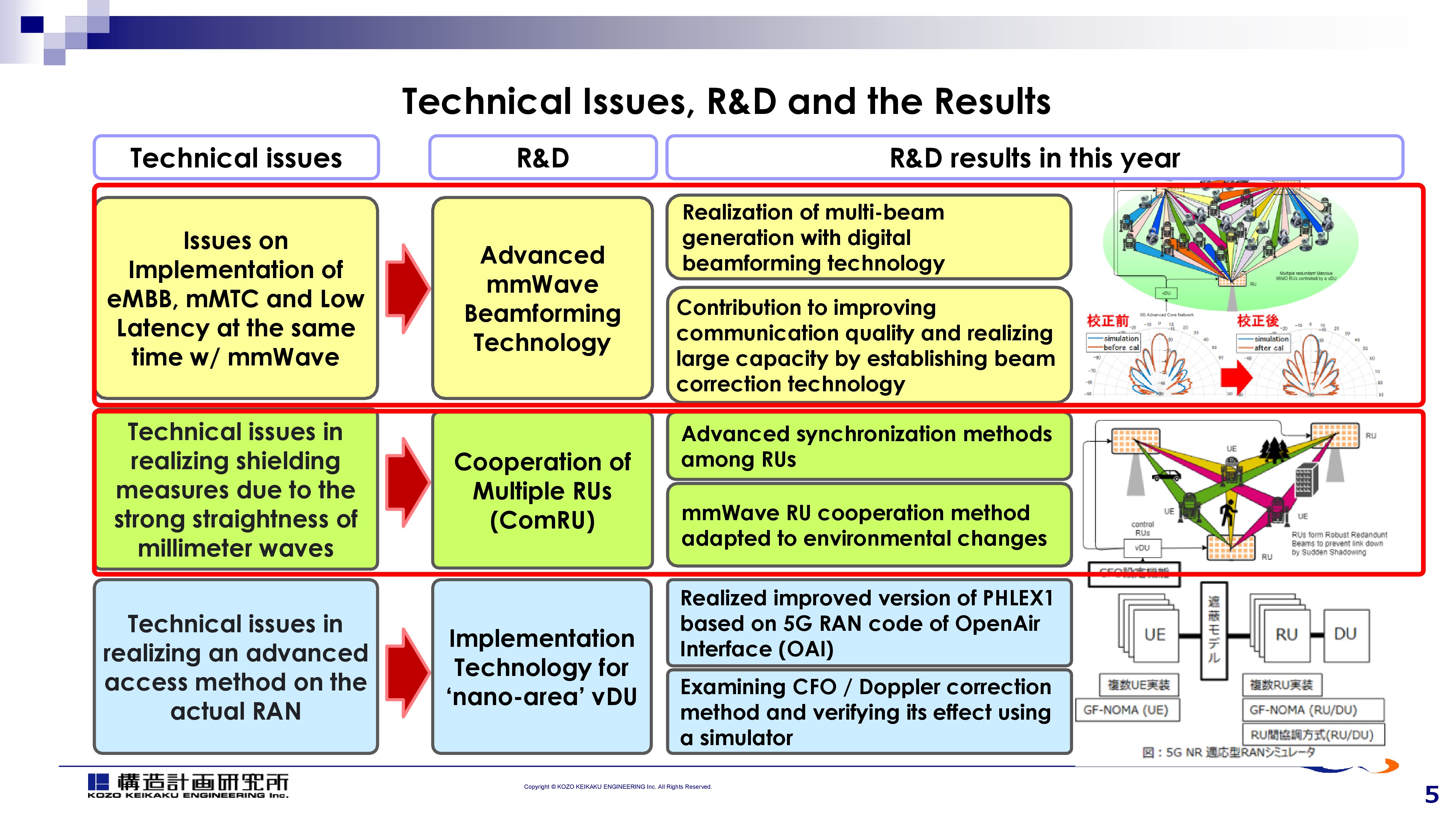 |
This chart describes structure of our research project.
Our research consists of three research components,
In this presentation, I mainly talk about Advanced mmWave Beamforming Technology.
I'll also introduce briefly about the second part, Research about Cooperation of Multiple RUs.
|
| ICACT20210169 Slide.06
[Big Slide]
|
Chrome Click!! |
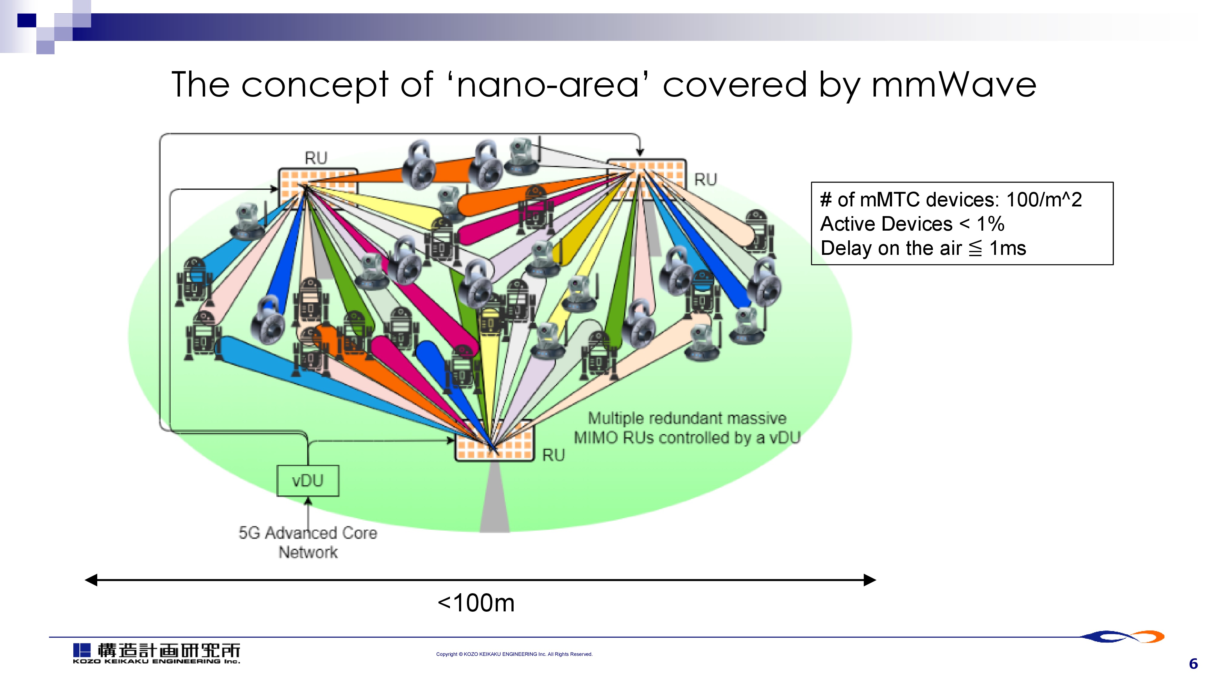 |
This slide shows the concept of ‘nano-area’.
It is a small area, filled with a lot of terminals, mainly, mMTC devices.
The area is covered with multiple RUs. Each RU equips mmWave beam antenna. |
| ICACT20210169 Slide.07
[Big Slide]
|
Chrome Click!! |
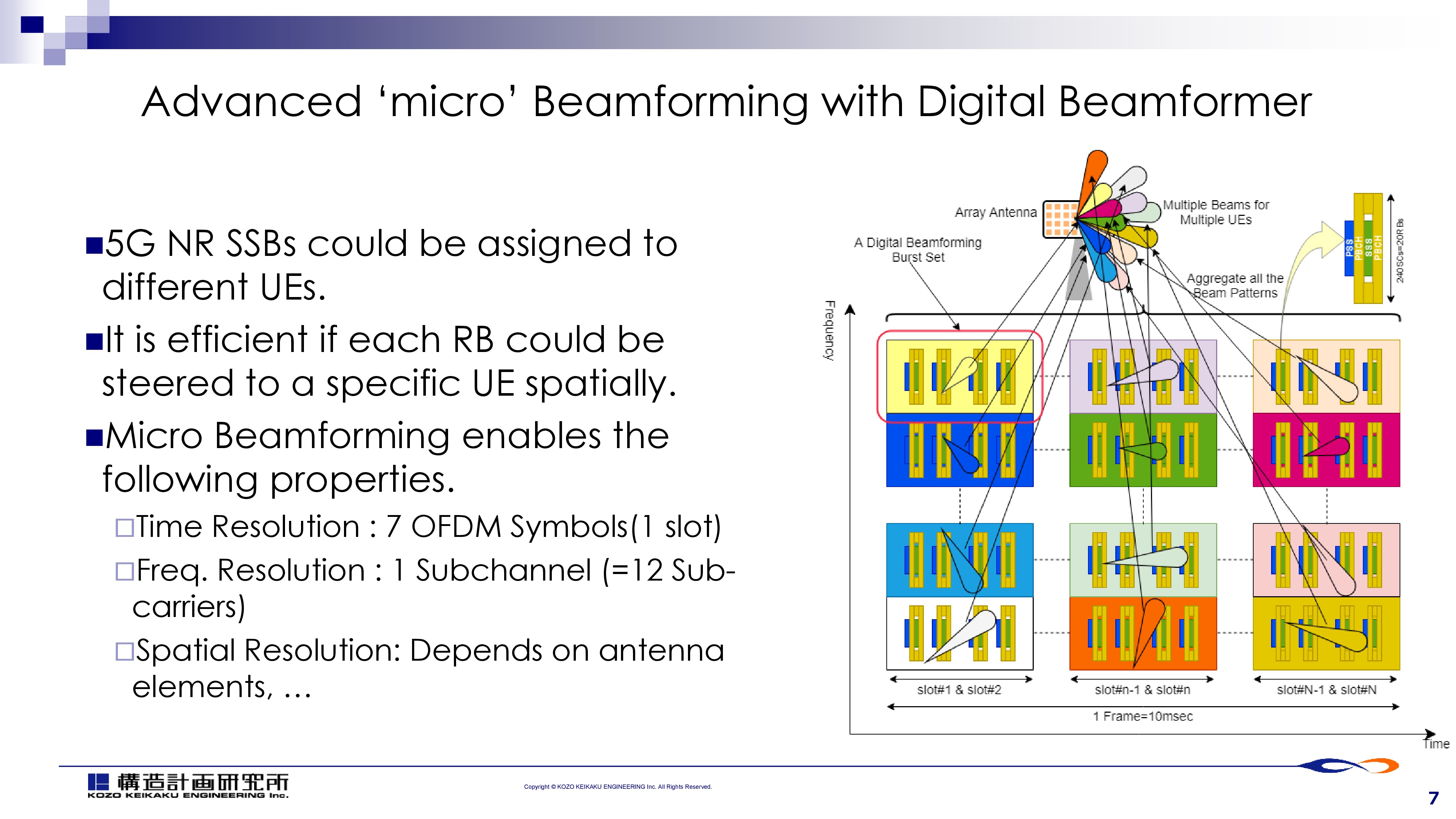 |
This slide shows basic concept of the Advanced ‘micro’ beamforming.
The figure shows 5G NR frame structure. Each 5G NR SSB (Synchronization Signal Block) could be formed independent beam for each UE by Ditigal beamforming.
This means it is capable of covering multiple UEs at different location in the same time period. |
| ICACT20210169 Slide.08
[Big Slide]
|
Chrome Click!! |
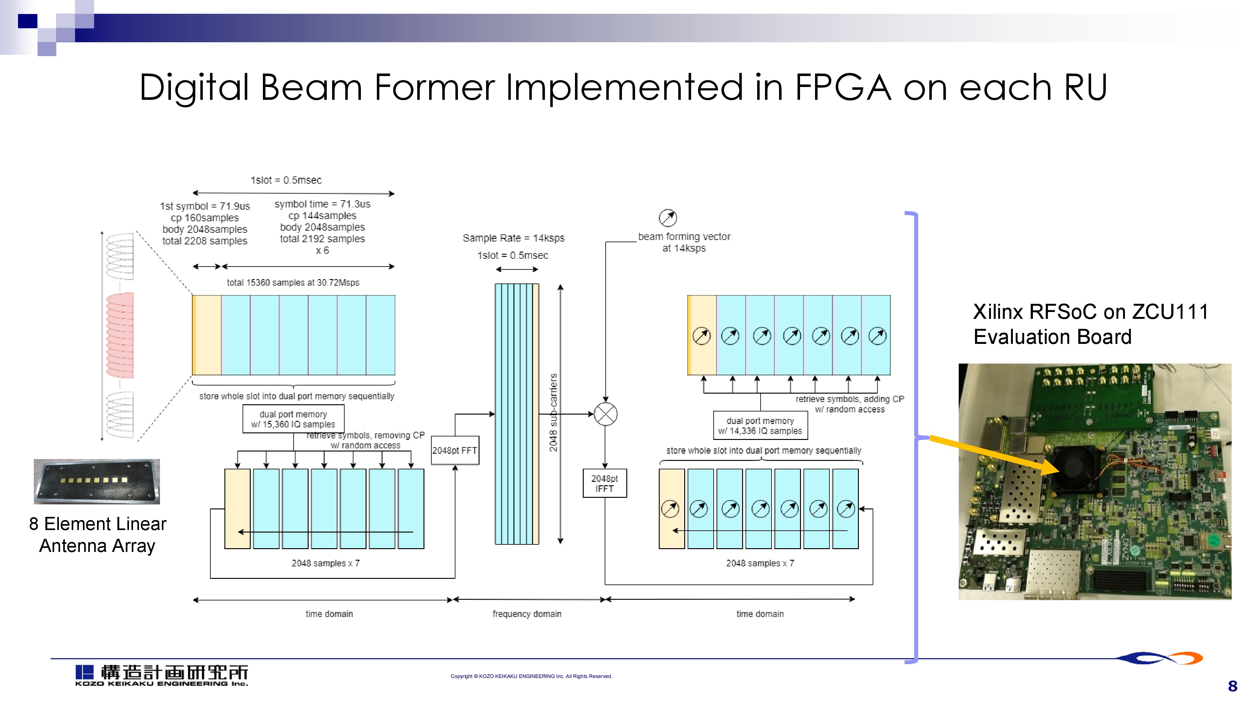 |
To implement the digital beamforming, we implemented a prototype of the digital beamformer on a FPGA, Xilinx RFSoC, which has on chip 8ch AD/DA converters.
This slied shows the actual DSP circuit(RX part) on the FPGA. It just controls one I-Q stream contains up to 2048 subcarriers.
Each subcarrier’s phase and amplitude is fully digitally controlled and mixed to have beam gain. |
| ICACT20210169 Slide.09
[Big Slide]
|
Chrome Click!! |
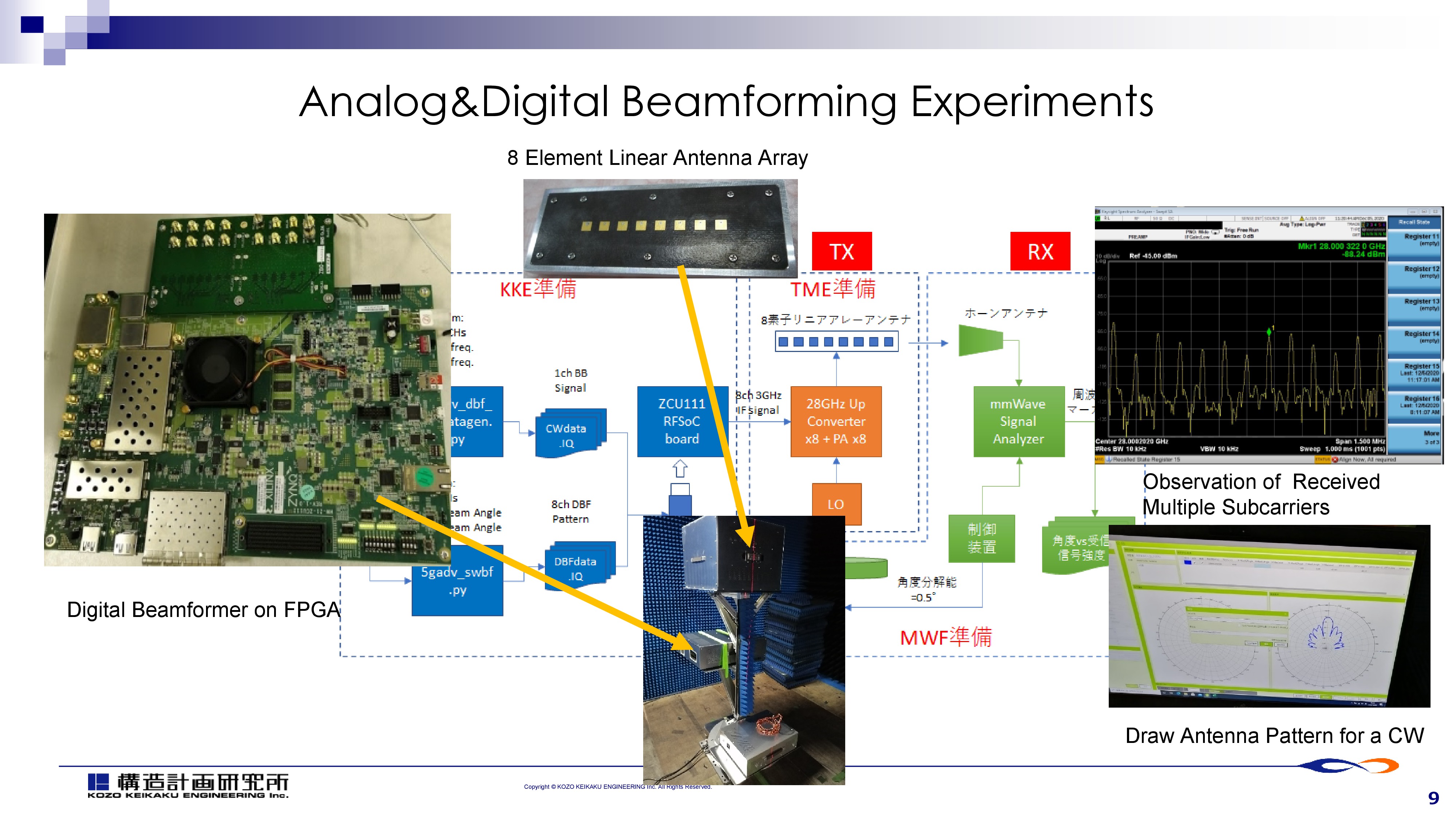 |
Our research group just finished some of the fundamental experiments regarding analog and digital beamforming at 28GHz later this year.
This slide shows our digital beamforming experiments conducted on last December. |
| ICACT20210169 Slide.10
[Big Slide]
|
Chrome Click!! |
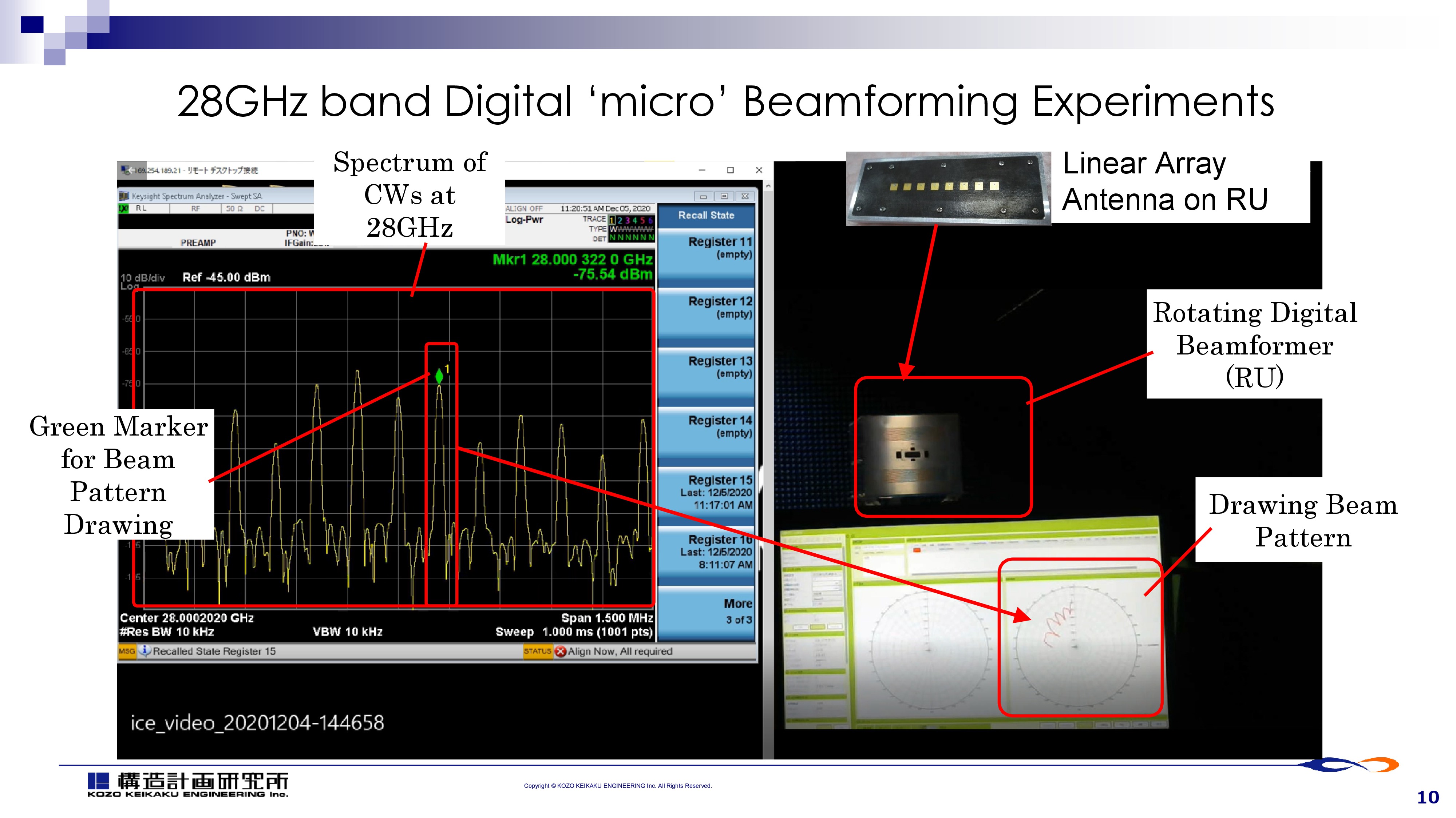 |
On the right half of the screen ,shows a digital beamforming RU equipped with an 8-element linear array antenna, rotates in an anechoic chamber while transmitting radio waves in 28 GHz band.
In this video, the radio wave consists of twelve constant waves, observed on the spectrum analyzer. Each CW wave is regarded as a 5G NR SSB (Synchronizing Signal Block) in this experiment, and signals with different phases are configured for each CW and antenna element by the digital beam former. |
| ICACT20210169 Slide.11
[Big Slide]
|
Chrome Click!! |
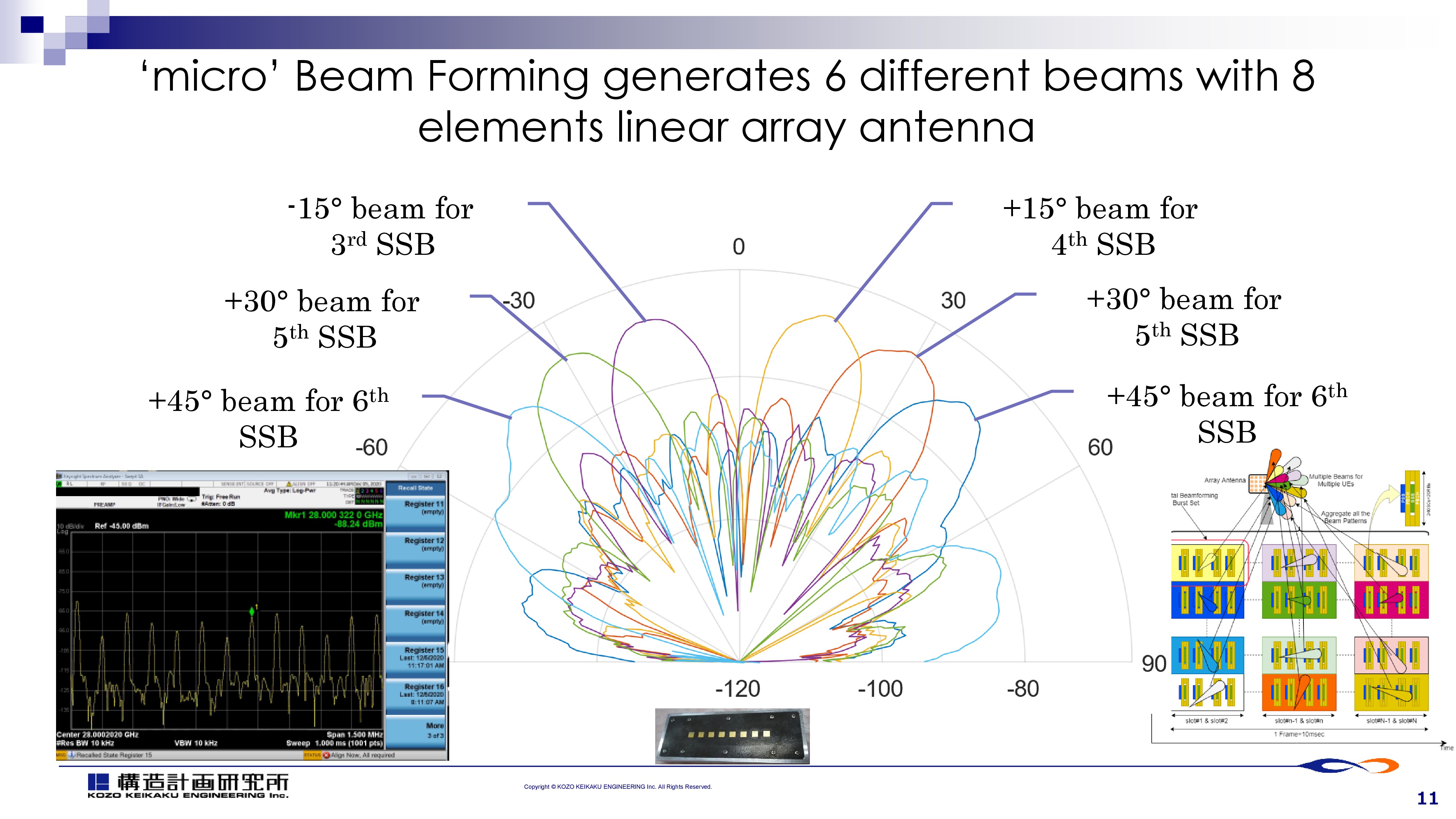 |
After the experiment last slide, I plotted the directional characteristics graph for six constant waves.
Each subcarrier is formed to different orientation with 15 degree interval with a eight element linear array antenna.
This is the result of our digital beamforming experiment. |
| ICACT20210169 Slide.12
[Big Slide]
|
Chrome Click!! |
 |
I briefly look through another research topic.
I told you that our ‘nano-area’ is covered with mmWave.
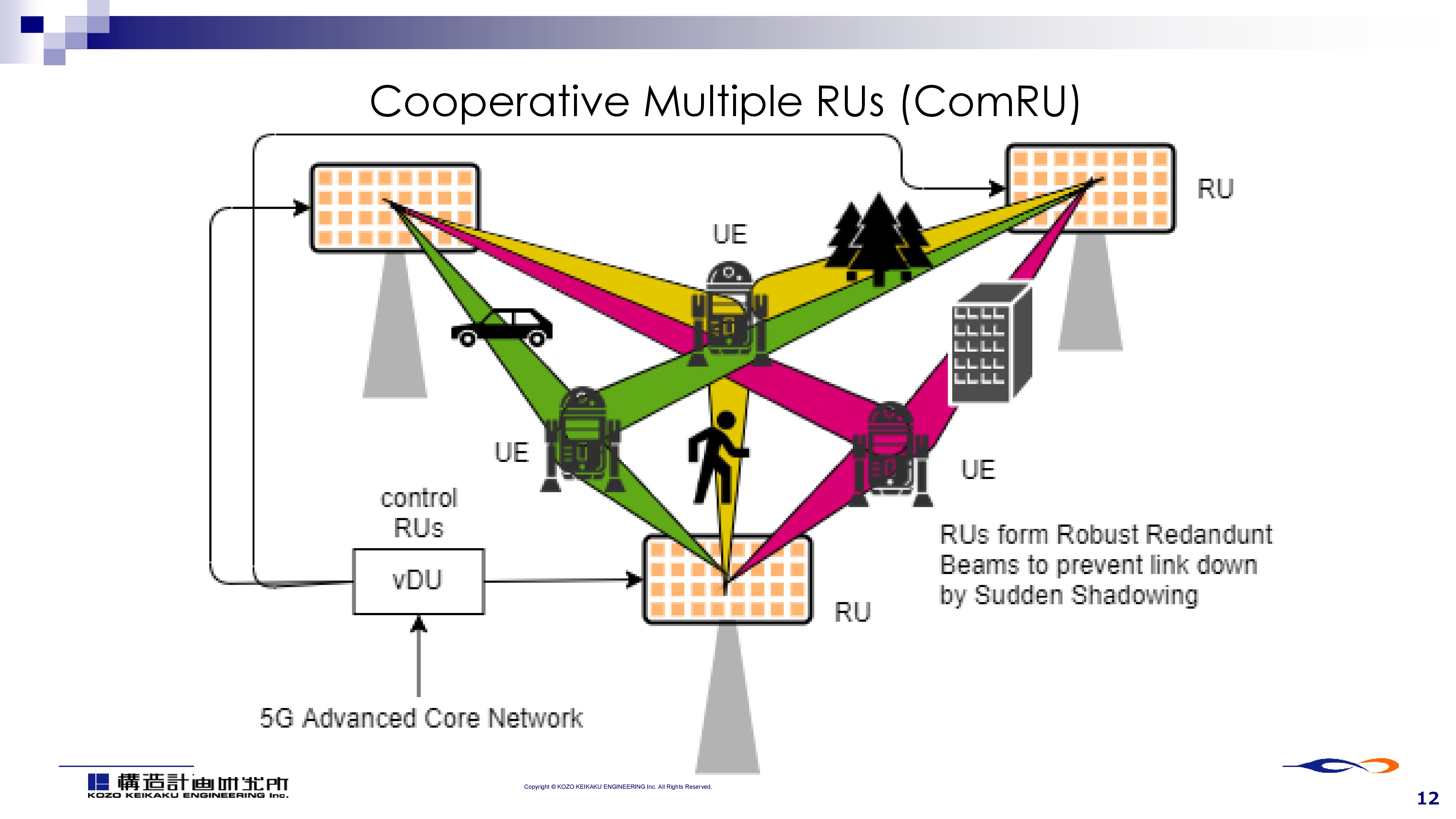
mmWave is known as it’s extreme distance loss.
That’s the reason why our research is focusing on advanced technology of beam antenna.
On the other side, mmWave is also known as it’s vulnerability to obstructions.
To overcome this, it is necessary to deploy redundant RU on the distributed locations.
It’s like an idea of ‘CoMP(Cooperative Multi Point) for mmWave at nano-area. |
| ICACT20210169 Slide.13
[Big Slide]
|
Chrome Click!! |
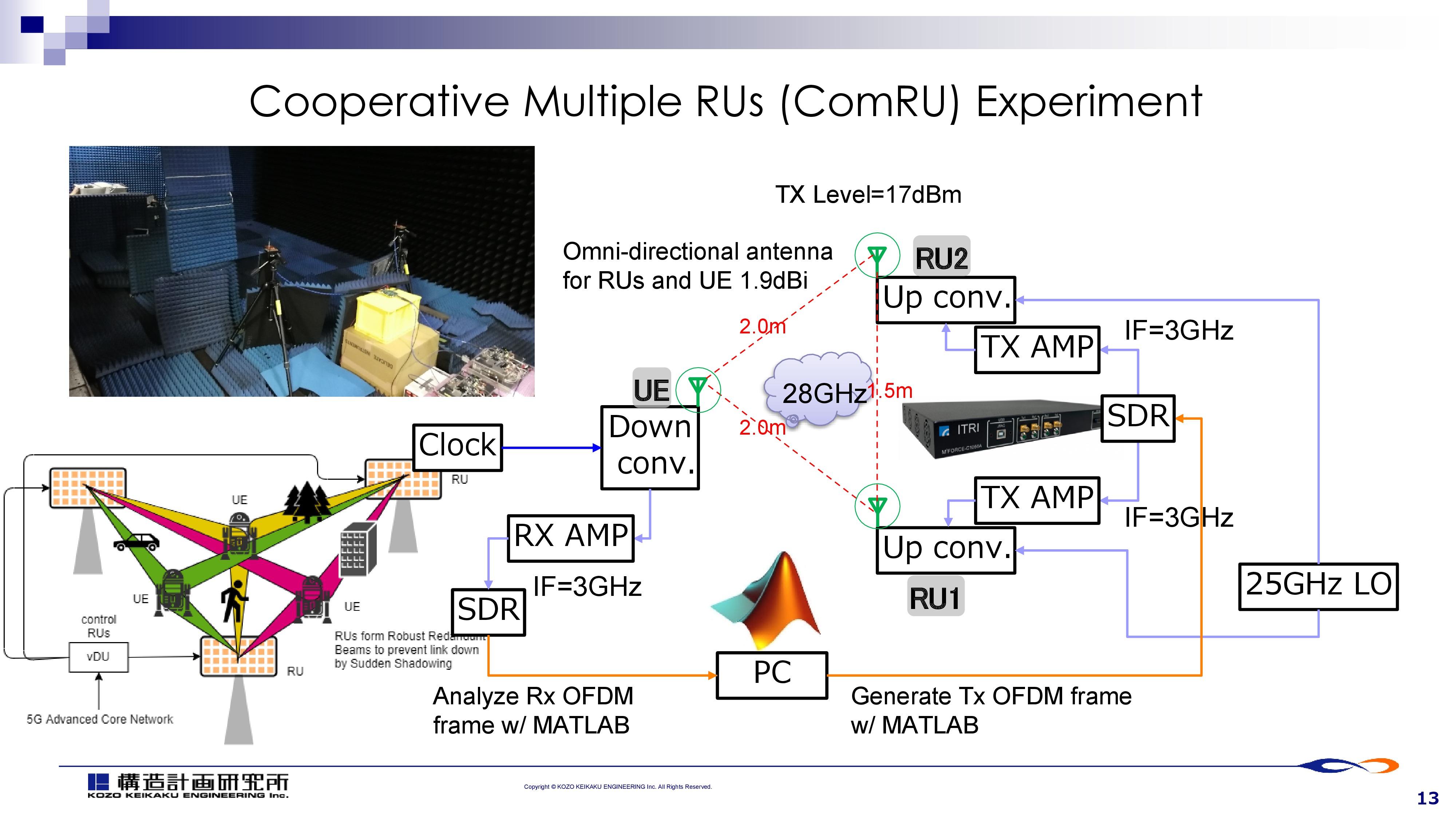 |
We conducted an experiment in an anechoic chamber using two 28GHz RUs and a UE, both equipped with omni directional antenna. |
| ICACT20210169 Slide.14
[Big Slide]
|
Chrome Click!! |
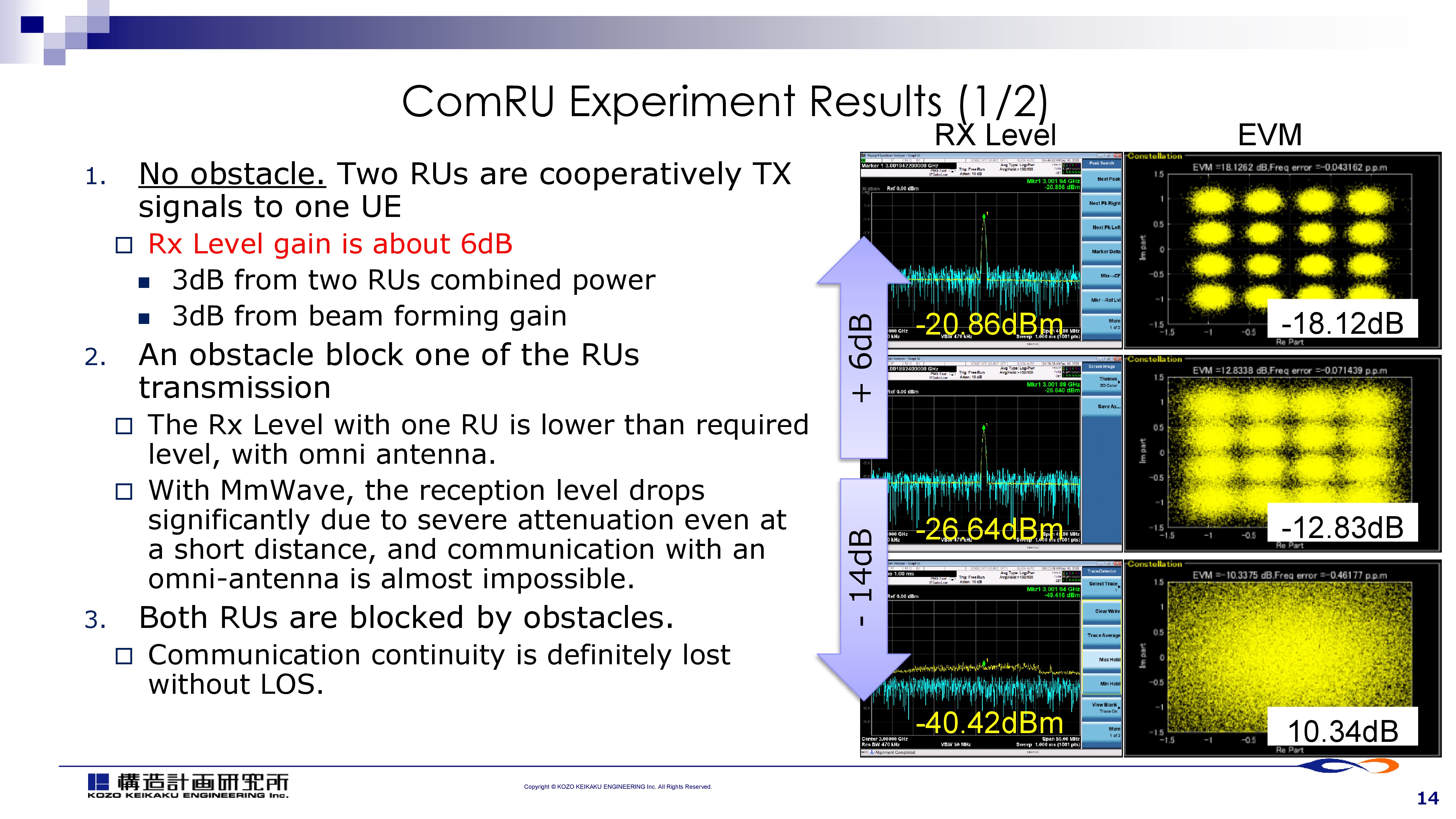 |
Through the experiment, we confirmed the effects of cooperation of multiple RUs. |
| ICACT20210169 Slide.15
[Big Slide]
|
Chrome Click!! |
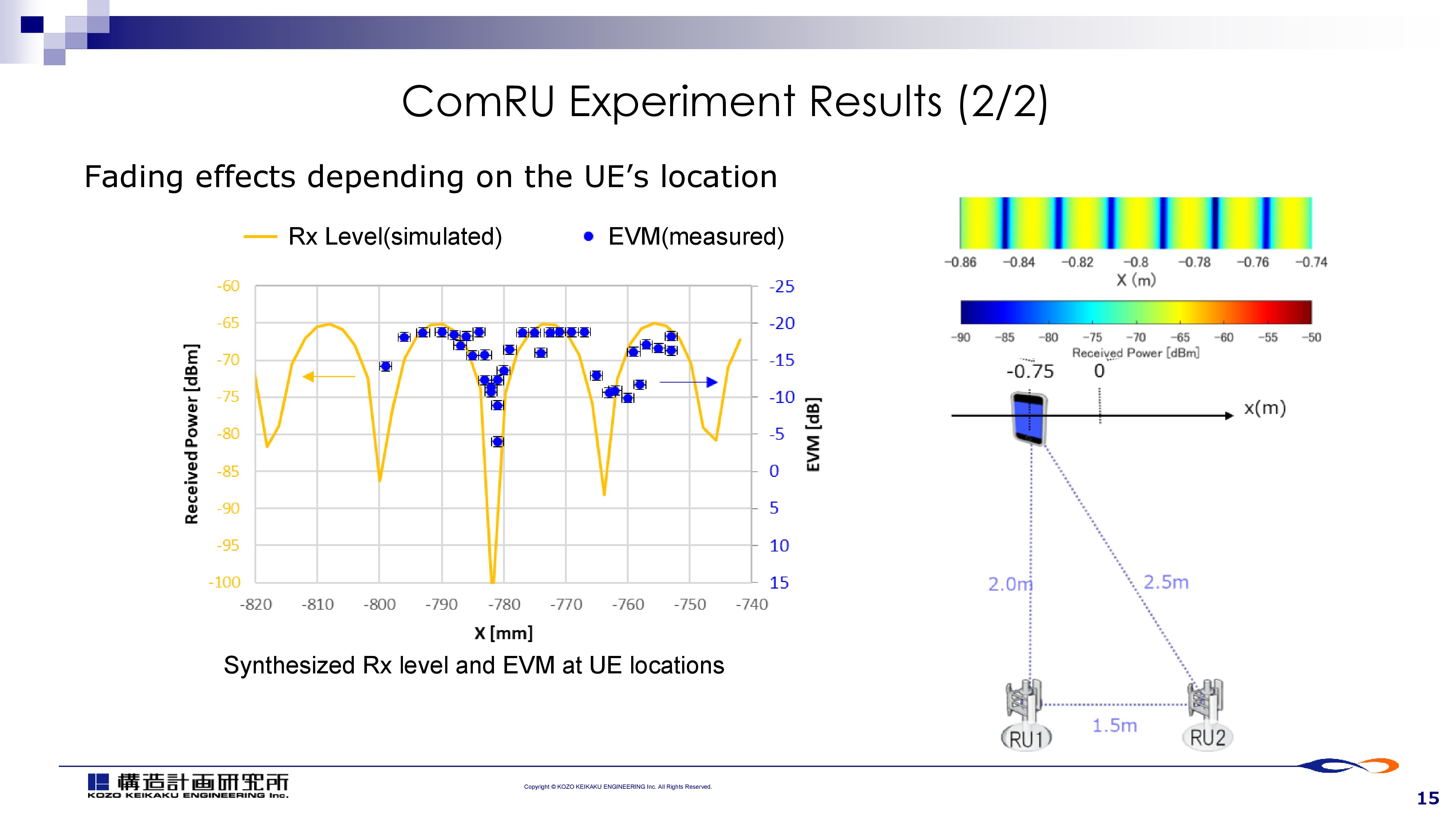 |
We also observed some fading effects.
Since millimeter waves have a short wavelength, the fading situation changes significantly even if the terminal moves a few millimeters.
Especially for the multiple RU cooperation, fast channel estimation and fine control of channel coding is required. |
| ICACT20210169 Slide.16
[Big Slide]
|
Chrome Click!! |
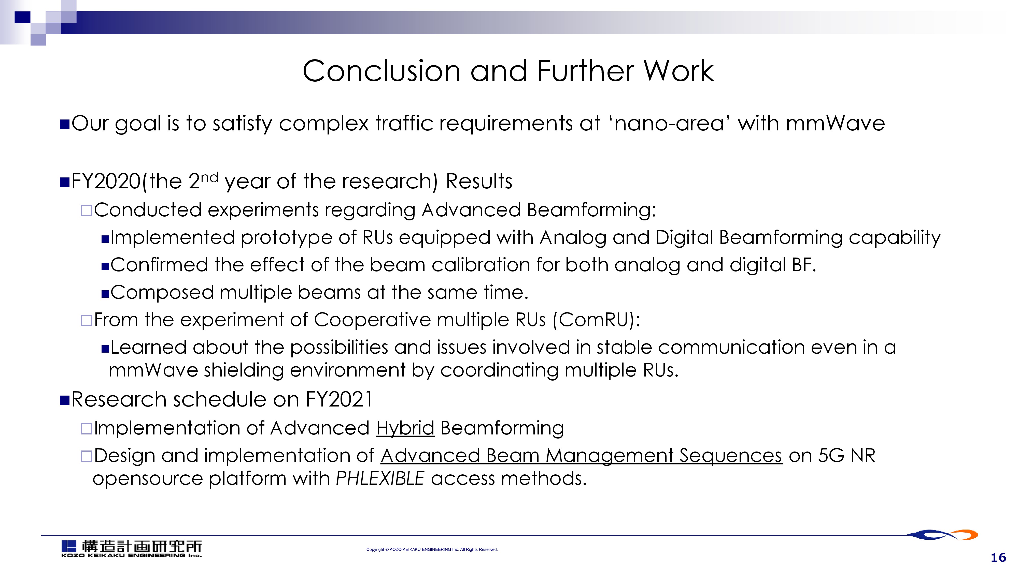 |
Conclusion and further work.
The second year of the entire 4 years research project, we conducted a series of experiments regarding mmWave beamforming, which yielded a number of suggestive results.
I also introduced our basic research results about cooperating multiple RUs.
Nex FY, we’ll try to implement Advanced digital-analog Hybrid Beamforming, Cooperative multiple RUs.
|
| ICACT20210169 Slide.17
[Big Slide]
|
Chrome Click!! |
 |
Thank you for your attention |















