 ICACT20260352 Slide.01
[Big Slide]
[YouTube] |
Chrome  Click!! |
 |
Hello everyone, my name is Li Zhanglong. I come from China. Its a great honor for me to attend this conference. The title of my presentation is Design of Low-Interception Short-Range Detection Signal for Co-Address MIMO-OCDM. Our research focus is on the design and processing of radar signals with low interception capability. |
| ICACT20260352 Slide.02
[Big Slide]
[YouTube] |
Chrome Click!! |
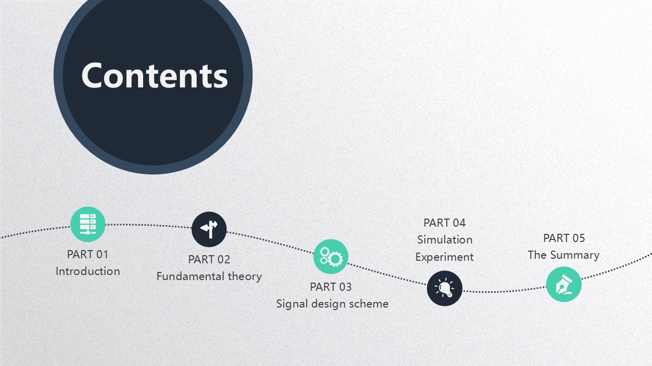 |
My speech mainly consists of the following five parts. The first part is the research background and significance; the second part is the basic theory; the third part is the signal design scheme; the fourth part is the simulation verification; and the fifth part is the summary. |
| ICACT20260352 Slide.03
[Big Slide]
[YouTube] |
Chrome Click!! |
 |
The first part mainly consists of two aspects. The first aspect is the research background and significance, while the second part is an overview of this study. |
| ICACT20260352 Slide.04
[Big Slide]
[YouTube] |
Chrome Click!! |
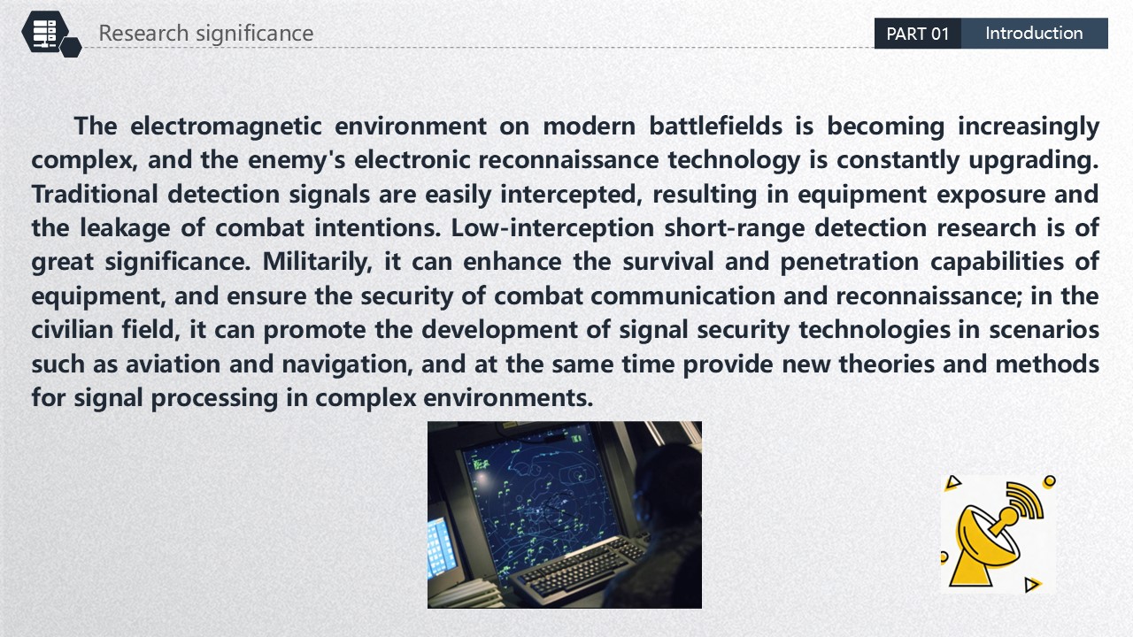 |
The electromagnetic environment on modern battlefields is becoming increasingly complex, and the enemys electronic reconnaissance technology is constantly upgrading. Traditional detection signals are easily intercepted, resulting in equipment exposure and the leakage of combat intentions. Low-interception short-range detection research is of great significance. Militarily, it can enhance the survival and penetration capabilities of equipment, and ensure the security of combat communication and reconnaissance; in the civilian field, it can promote the development of signal security technologies in scenarios such as aviation and navigation, and at the same time provide new theories and methods for signal processing in complex environments.
|
| ICACT20260352 Slide.05
[Big Slide]
[YouTube] |
Chrome Click!! |
 |
To improve the survivability of fuse, a co-address Multiple Input Multiple Output-Orthogonal Chirp Division Multiplexing (MIMO-OCDM) signal is designed, and a signal processing method of two-phase parametric accumulation is adopted to improve the signal-to-noise ratio of the echo signal. Firstly, the transmission power of a single signal is evenly distributed to each sub-chirp signal of the OCDM signal, and the sub-chirp signals are transmitted by the co-address MIMO radar to reduce the signal transmission power. Subsequently, the first coherent accumulation is carried out on multiple sub-chirp signals received by a single antenna, and the second coherent accumulation is performed on the echo signals received by multiple antennas to significantly enhance the signal-to-noise ratio of the echo signals.
|
| ICACT20260352 Slide.06
[Big Slide]
[YouTube] |
Chrome Click!! |
 |
The second part mainly introduces the MIMO radar system, the OCDM signal principle, and the principle of coherent accumulation respectively. |
| ICACT20260352 Slide.07
[Big Slide]
[YouTube] |
Chrome Click!! |
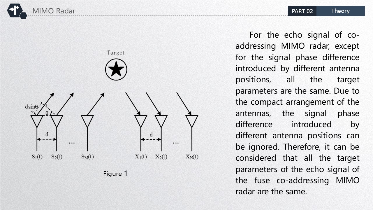 |
For the echo signal of co-addressing MIMO radar, except for the signal phase difference introduced by different antenna positions, all the target parameters are the same. Due to the compact arrangement of the antennas, the signal phase difference introduced by different antenna positions can be ignored. Therefore, it can be considered that all the target parameters of the echo signal of the fuse co-addressing MIMO radar are the same. |
| ICACT20260352 Slide.08
[Big Slide]
[YouTube] |
Chrome Click!! |
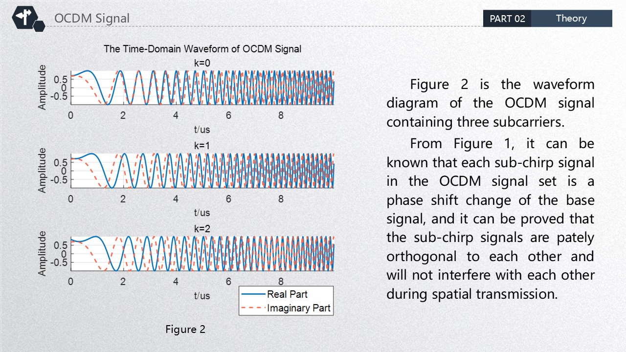 |
Figure 2 is the waveform diagram of the OCDM signal containing three subcarriers.
From Figure 1, it can be known that each sub-chirp signal in the OCDM signal set is a phase shift change of the base signal, and it can be proved that the sub-chirp signals are pately orthogonal to each other and will not interfere with each other during spatial transmission. |
| ICACT20260352 Slide.09
[Big Slide]
[YouTube] |
Chrome Click!! |
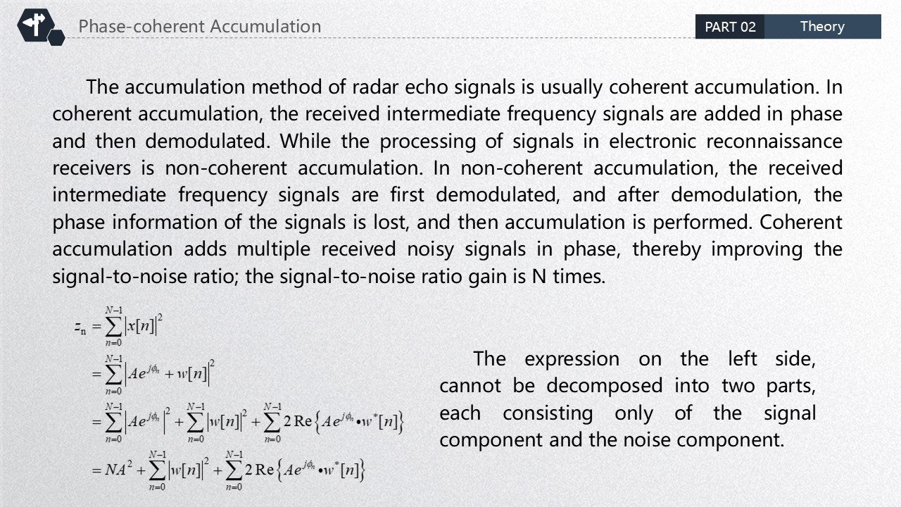 |
The accumulation method of radar echo signals is usually coherent accumulation. In coherent accumulation, the received intermediate frequency signals are added in phase and then demodulated. While the processing of signals in electronic reconnaissance receivers is non-coherent accumulation. In non-coherent accumulation, the received intermediate frequency signals are first demodulated, and after demodulation, the phase information of the signals is lost, and then accumulation is performed. Coherent accumulation adds multiple received noisy signals in phase, thereby improving the signal-to-noise ratio; the signal-to-noise ratio gain is N times.
The expression on the left side, cannot be decomposed into two parts, each consisting only of the signal component and the noise component.
|
| ICACT20260352 Slide.10
[Big Slide]
[YouTube] |
Chrome Click!! |
 |
The third part mainly involves the design scheme and feasibility analysis of low-interception short-range detection signals. |
| ICACT20260352 Slide.11
[Big Slide]
[YouTube] |
Chrome Click!! |
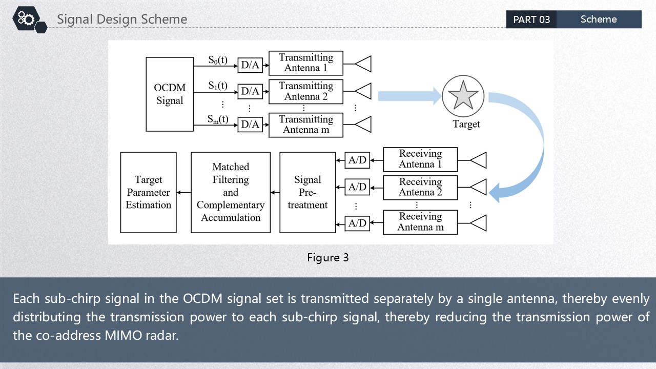 |
Each sub-chirp signal in the OCDM signal set is transmitted separately by a single antenna, thereby evenly distributing the transmission power to each sub-chirp signal, thereby reducing the transmission power of the co-address MIMO radar. |
| ICACT20260352 Slide.12
[Big Slide]
[YouTube] |
Chrome Click!! |
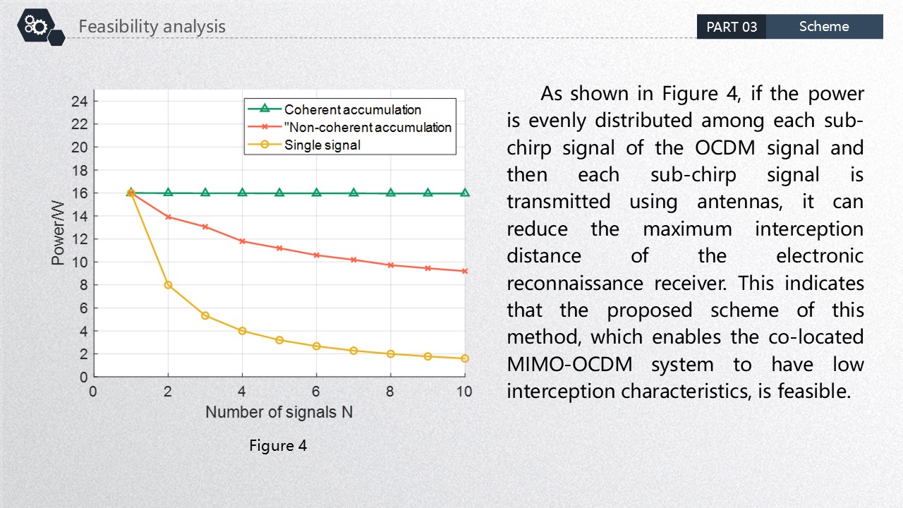 |
As shown in Figure 4, if the power is evenly distributed among each sub-chirp signal of the OCDM signal and then each sub-chirp signal is transmitted using antennas, it can reduce the maximum interception distance of the electronic reconnaissance receiver. This indicates that the proposed scheme of this method, which enables the co-located MIMO-OCDM system to have low interception characteristics, is feasible. |
| ICACT20260352 Slide.13
[Big Slide]
[YouTube] |
Chrome Click!! |
 |
The fourth part first analyzes the detection performance of the designed signal. Only when the detection task can be accomplished can the low interception capability be analyzed, and then the low interception performance will be analyzed. |
| ICACT20260352 Slide.14
[Big Slide]
[YouTube] |
Chrome Click!! |
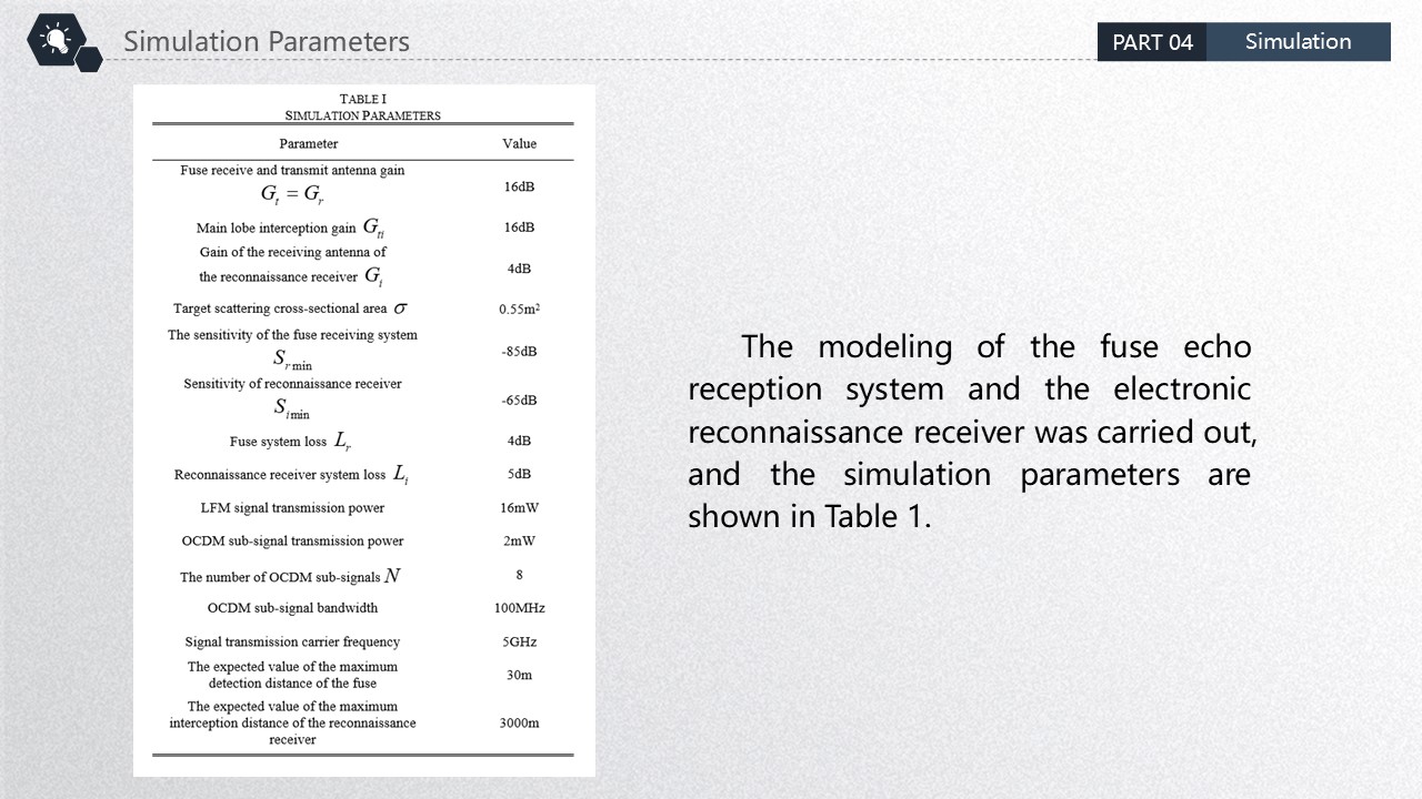 |
The modeling of the fuse echo reception system and the electronic reconnaissance receiver was carried out, and the simulation parameters are shown in Table 1. |
| ICACT20260352 Slide.15
[Big Slide]
[YouTube] |
Chrome Click!! |
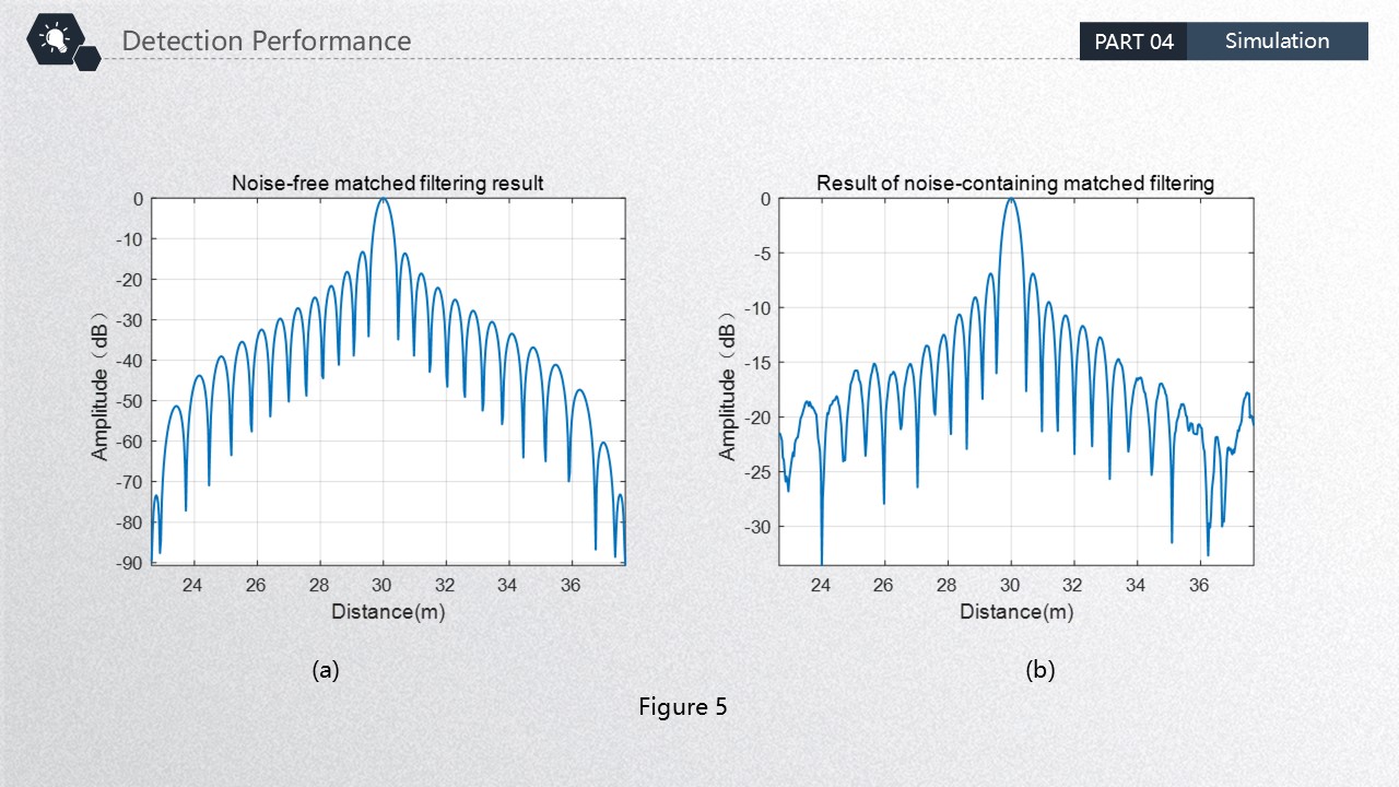 |
As shown in Figure 5, the matched filtering result of a single OCDM sub-chirp signal reaches its peak at 30m, indicating that the OCDM sub-chirp signal can successfully complete the matched filtering process. Then, the first phase coherent accumulation is performed on the signal received by a single antenna. |
| ICACT20260352 Slide.16
[Big Slide]
[YouTube] |
Chrome Click!! |
 |
As shown in Figure 5, the matched filtering result of a single OCDM sub-chirp signal reaches its peak at 30m, indicating that the OCDM sub-chirp signal can successfully complete the matched filtering process. Then, the first phase coherent accumulation is performed on the signal received by a single antenna. |
| ICACT20260352 Slide.17
[Big Slide]
[YouTube] |
Chrome Click!! |
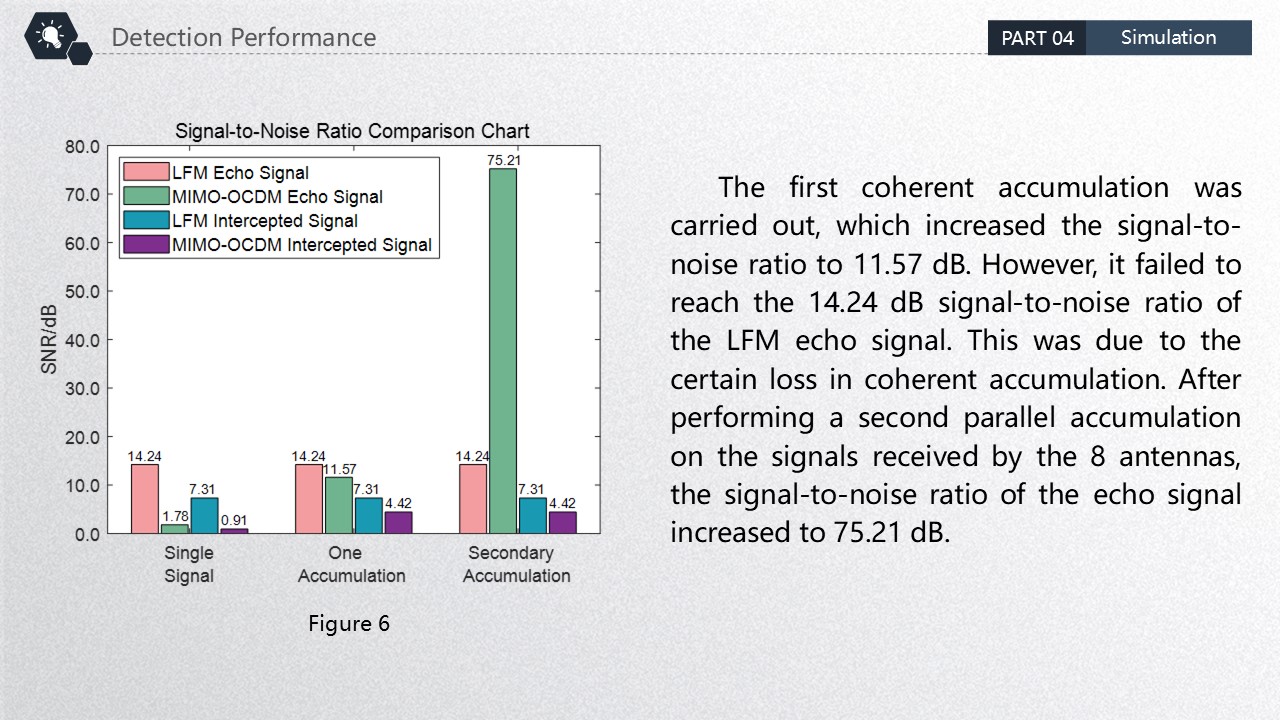 |
The first coherent accumulation was carried out, which increased the signal-to-noise ratio to 11.57 dB. However, it failed to reach the 14.24 dB signal-to-noise ratio of the LFM echo signal. This was due to the certain loss in coherent accumulation. After performing a second parallel accumulation on the signals received by the 8 antennas, the signal-to-noise ratio of the echo signal increased to 75.21 dB. |
| ICACT20260352 Slide.18
[Big Slide]
[YouTube] |
Chrome Click!! |
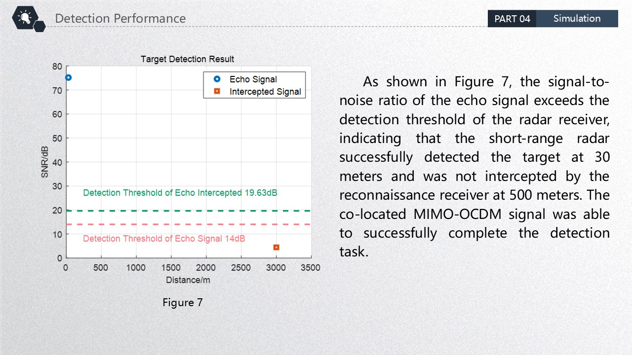 |
As shown in Figure 7, the signal-to-noise ratio of the echo signal exceeds the detection threshold of the radar receiver, indicating that the short-range radar successfully detected the target at 30 meters and was not intercepted by the reconnaissance receiver at 500 meters. The co-located MIMO-OCDM signal was able to successfully complete the detection task. |
| ICACT20260352 Slide.19
[Big Slide]
[YouTube] |
Chrome Click!! |
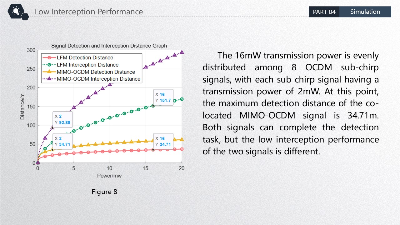 |
The 16mW transmission power is evenly distributed among 8 OCDM sub-chirp signals, with each sub-chirp signal having a transmission power of 2mW. At this point, the maximum detection distance of the co-located MIMO-OCDM signal is 34.71m. Both signals can complete the detection task, but the low interception performance of the two signals is different. |
| ICACT20260352 Slide.20
[Big Slide]
[YouTube] |
Chrome Click!! |
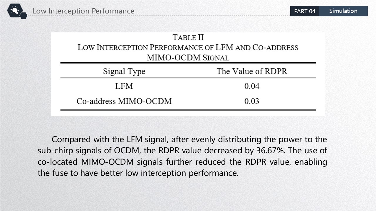 |
Compared with the LFM signal, after evenly distributing the power to the sub-chirp signals of OCDM, the RDPR value decreased by 36.67%. The use of co-located MIMO-OCDM signals further reduced the RDPR value, enabling the fuse to have better low interception performance. |
| ICACT20260352 Slide.21
[Big Slide]
[YouTube] |
Chrome Click!! |
 |
The fifth part is the conclusion. |
| ICACT20260352 Slide.22
[Big Slide]
[YouTube] |
Chrome Click!! |
 |
This paper designs co-located MIMO-OCDM signals to reduce the transmission power of the signals, thereby reducing the maximum interception distance of the electronic reconnaissance receiver. After the power of the LFM signal is evenly distributed to each co-located MIMO-OCDM sub-chirp signal, the maximum interception distance of the electronic reconnaissance receiver decreased by 58.81 meters, and the working factor decreased by 36.67%. The designed co-located MIMO-OCDM signals have good low-interception performance and have certain engineering application value. |
| ICACT20260352 Slide.23
[Big Slide]
[YouTube] |
Chrome Click!! |
 |
Thank you for listening. |
| ICACT20260352 Slide.24
[Big Slide]
[YouTube] |
Chrome Click!! |
 |
https://youtu.be/T4pU1gXvFnc |















