 ICACT20220296 Slide.01
[Big Slide]
[YouTube] |
Chrome  Click!! |
 |
Hi everyone, I am Rabiul Islam Sikder. I am a PhD student at KAIST Metaphotonics lab. Today, I am going to talk about Different Multi-layer Photonic Configurations for Light Filtering in Optical Communications. |
| ICACT20220296 Slide.02
[Big Slide]
[YouTube] |
Chrome Click!! |
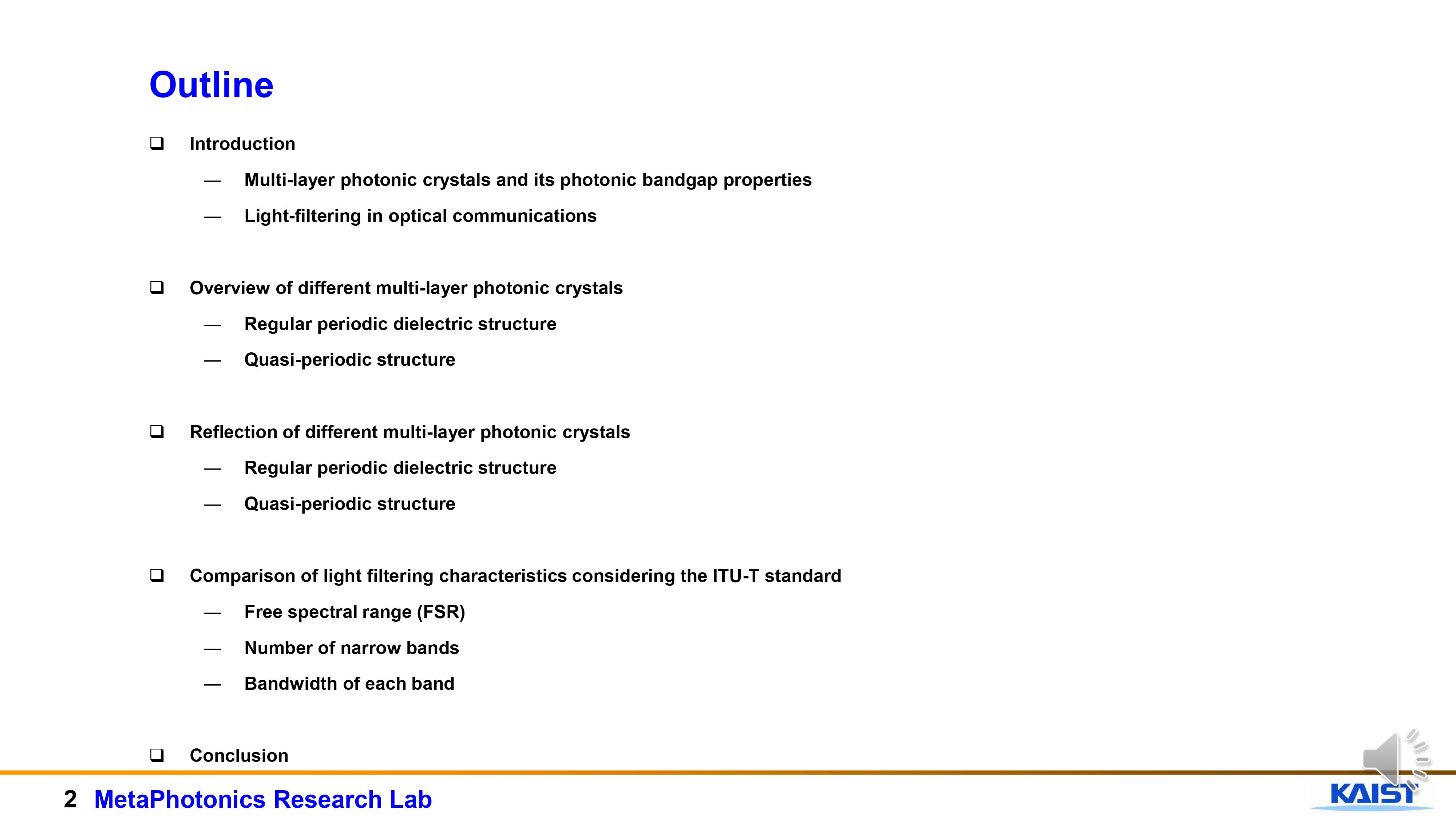 |
Here is the outline of my presentation. I will start my presentation with a brief explanation of multi-layer photonic crystals and its photonic bandgap properties. Then I will give an overview of different multi-layer photonic crystals. I will discuss about the regular periodic dielectric structure and quasi periodic structure. I will then show the reflection spectrum of different multi-layer photonic crystals. Then using the reflection spectrum I will make a comparison of light filtering characteristics considering the ITU-T standard taking into consideration of free spectral range (FSR), number of narrow bands and bandwidth of each band.
|
| ICACT20220296 Slide.03
[Big Slide]
[YouTube] |
Chrome Click!! |
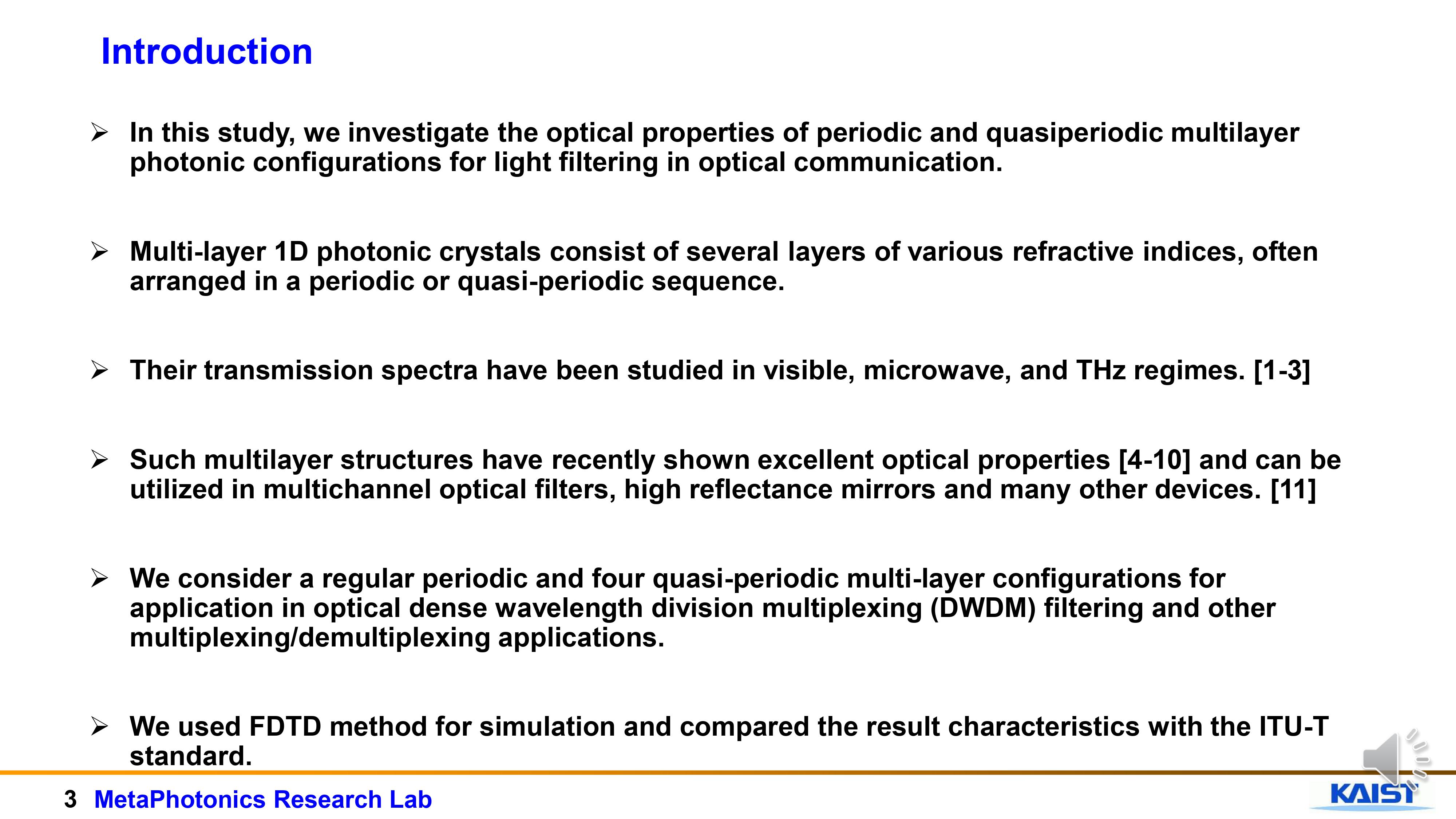 |
In this study, we investigated the optical properties of periodic and quasiperiodic multilayer structures and its application for light filtering in optical communication.
Multi-layer 1-dimensional photonic crystals consist of several layers of various refractive indices, often arranged in a periodic or quasi-periodic sequence.
Such multilayer photonic structures have recently shown excellent optical properties and can be utilized in multi-channel optical filters and high reflectance mirrors.
We consider a regular periodic and four quasi-periodic multi-layer configurations for applications in optical dense wavelength division multiplexing (DWDM) filtering and other multiplexing/de-multiplexing applications
We used FDTD method for simulation and compared the result characteristics with the ITU-T standard.
|
| ICACT20220296 Slide.04
[Big Slide]
[YouTube] |
Chrome Click!! |
 |
Let us talk about Photonic crystals and photonic bandgap
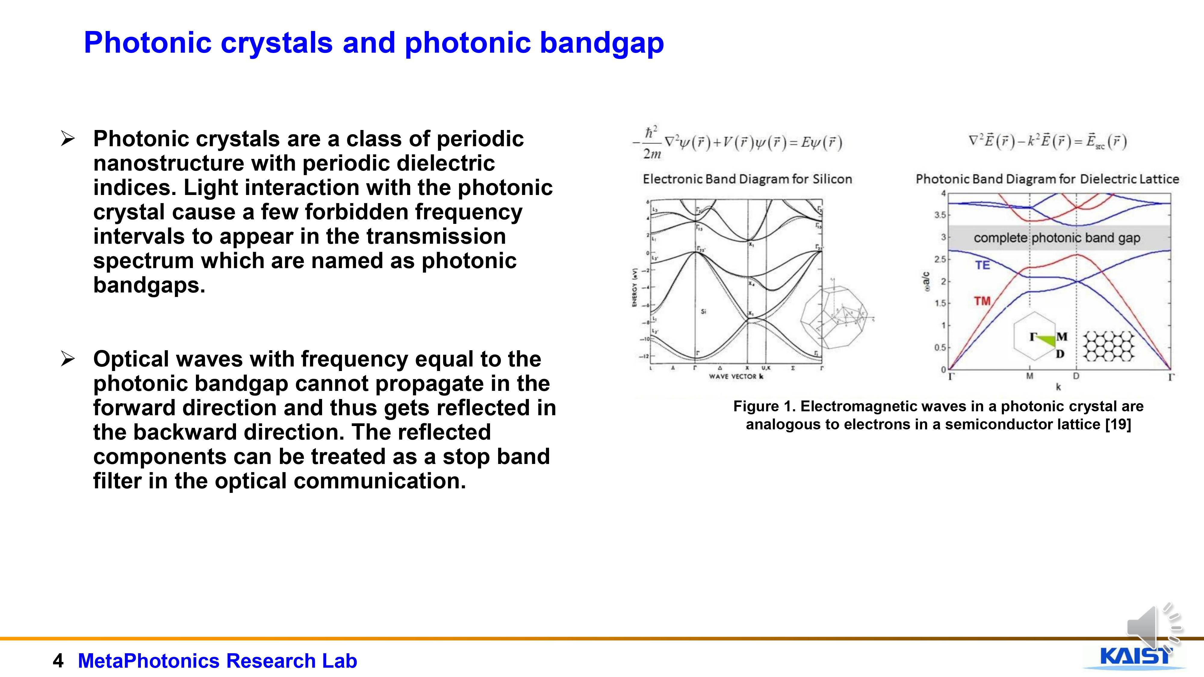
Photonic crystals are a class of periodic nanostructure with periodic dielectric indices. Light interaction with the photonic crystal cause a few forbidden frequency intervals to appear in the transmission spectrum which are named as photonic bandgaps.
We know that Schrodinger equation describe the flow of electron in a periodic potential. Such as the flow of electron in a semiconductor.
If we analyze the electromagnetic wave equation in the same way, we get bands. We can control the EM wave in these periodic structures the same way we control electroncs in silicon (the semiconductor). So like electron band we have photonic band. In analogy with the band diagram, we call this photonic band diagram.
In the Photonic band gap (Forbidden energy): photonic crystal act like an insulator and act like a mirror. They reflect light.
Optical waves with frequency equal to the photonic bandgap cannot propagate in the forward direction and thus gets reflected in the backward direction. The reflected components can be treated as a stop band filter in the optical communication
|
| ICACT20220296 Slide.05
[Big Slide]
[YouTube] |
Chrome Click!! |
 |
Next, we will talk about the regular periodic multi-layer structure and four quasi-periodic multi-layer structure namely: Cantor sequence, Fibonacci sequence, Thue-Morese sequence and Rudin Shapiro sequence
The structure we studied involved two types of layers, silicon and silica respectively represented by A and B throughout this presentation.
|
| ICACT20220296 Slide.06
[Big Slide]
[YouTube] |
Chrome Click!! |
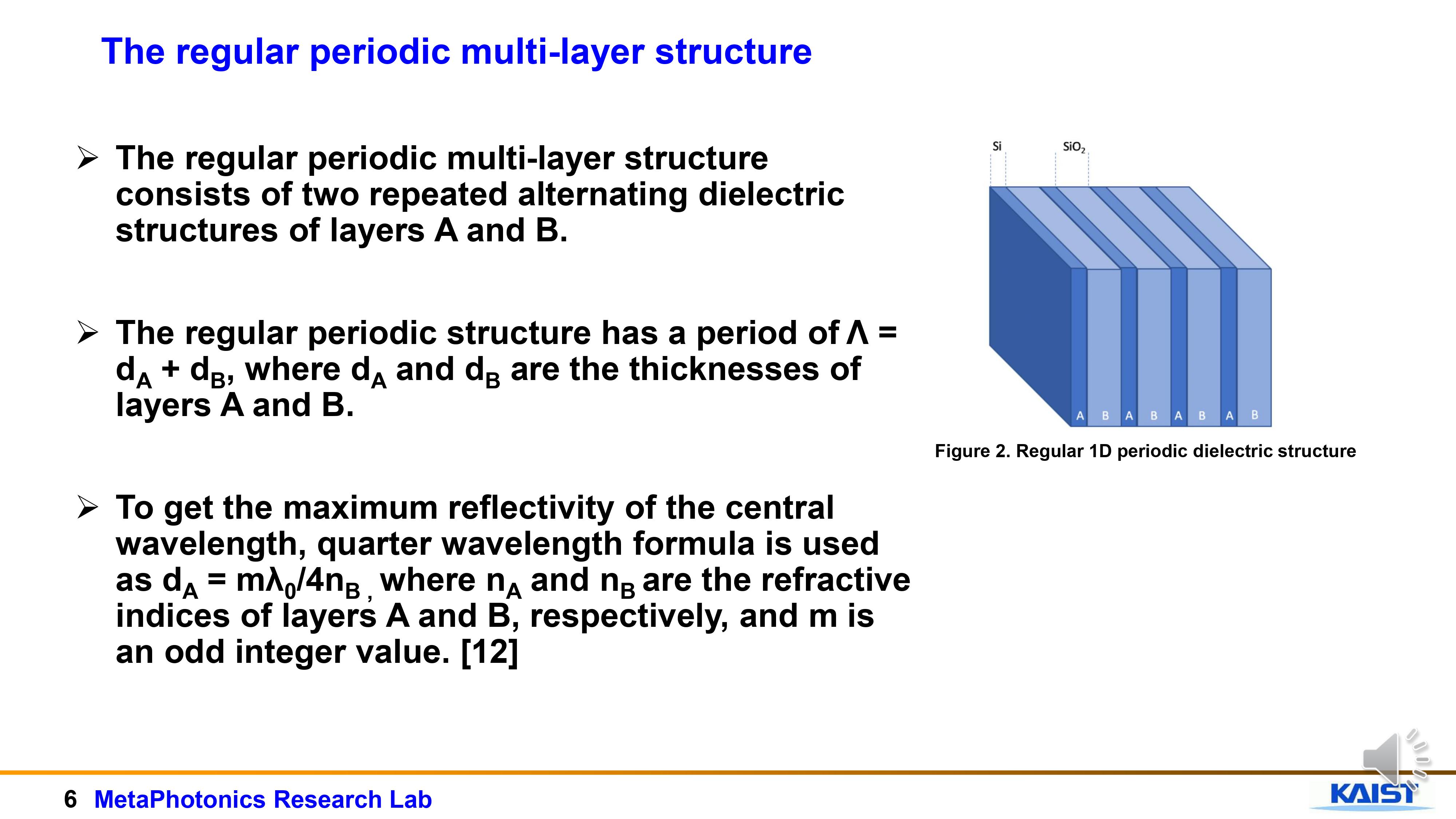 |
The figure on the right side shows the regular periodic multi-layer structure. It consists of two different repeated and alternating dielectric structures of layers A and B.
The regular periodic structure has a period of Λ = dA + dB, where dA and dB are the thicknesses of layers A and B
To get the maximum reflectivity at the central wavelength of 1550nm, quarter wavelength formula is used as dA = mλ0/4nB , where nA and nB are the refractive indices of layers A and B, respectively, and m is an odd integer value.
|
| ICACT20220296 Slide.07
[Big Slide]
[YouTube] |
Chrome Click!! |
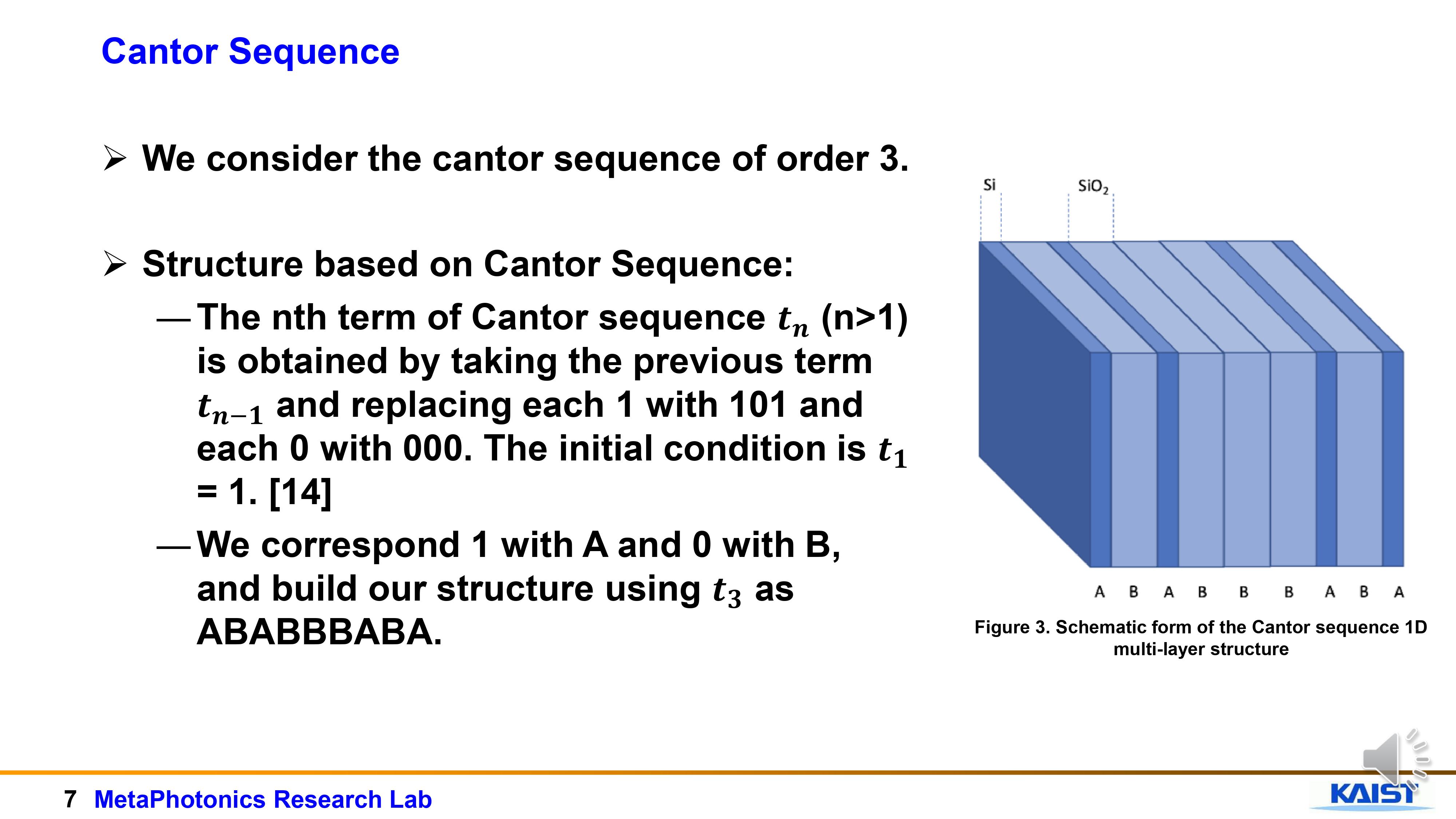 |
Here we show the cantor sequence structure.
Structure based on Cantor Sequence:
The nth term of Cantor sequence tn (n>1) is obtained by taking the previous term tn-1 and replacing each 1 with 101 and each 0 with 000. The initial condition is t1 = 1.
We denote 1 with A and 0 with B, and build our structure using t3 as ABABBBABA.
|
| ICACT20220296 Slide.08
[Big Slide]
[YouTube] |
Chrome Click!! |
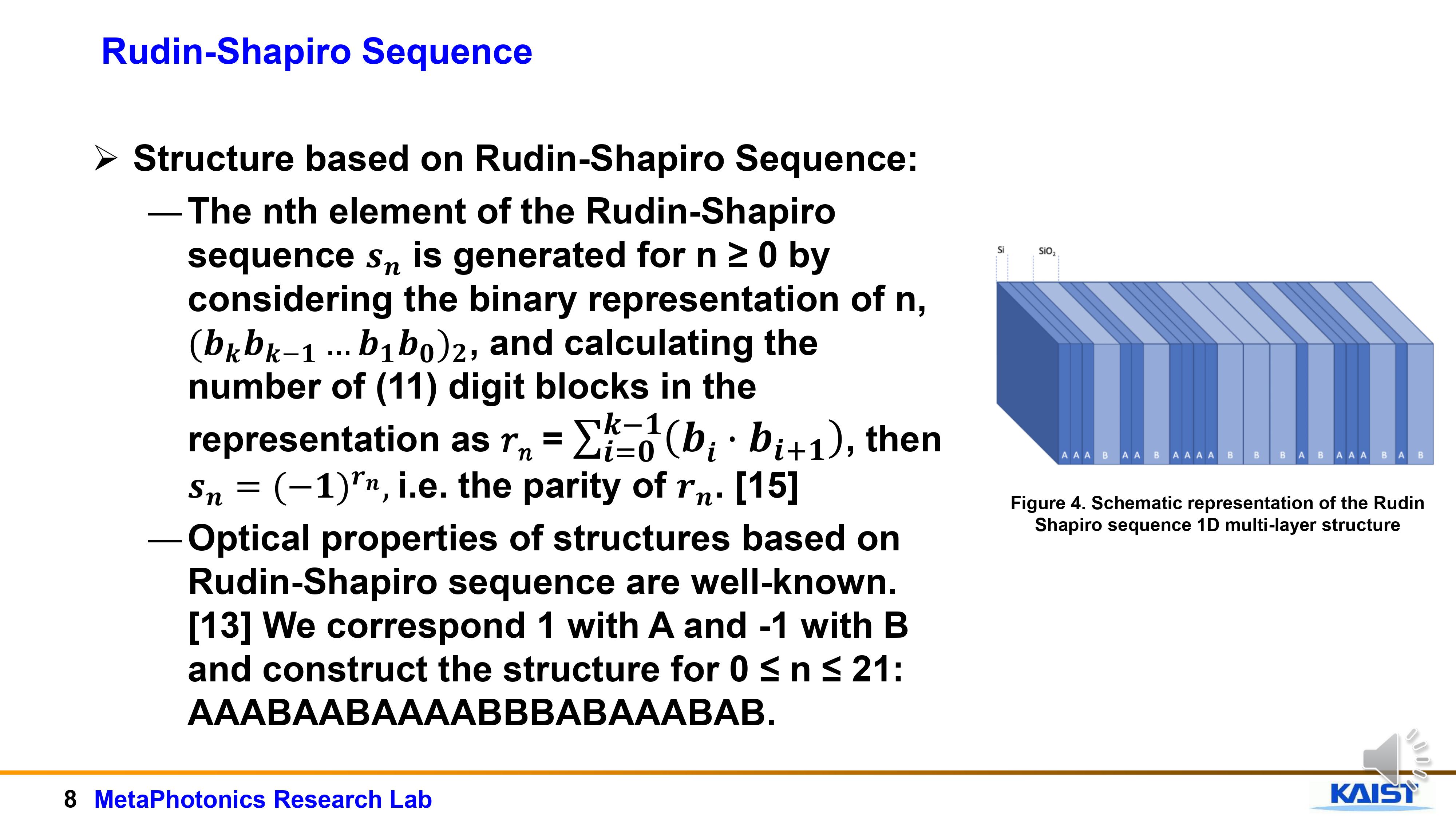 |
This is the structure of Rudin – Shapiro .
The nth element of the Rudin-Shapiro sequence Sn is generated for n ≥ 0 by considering the binary representation of n, (bkbk-1…b1b0)2 , and calculating the number of (11) digit blocks in the representation as 𝑟𝑛 = ∑_(𝒊=𝟎)^(𝒌−𝟏)▒(𝒃𝒊〖·𝒃〗_(𝒊+𝟏) ) , then 𝒔_𝒏 𝒊𝒔 𝒆𝒒𝒖𝒂𝒍 𝒕𝒐 the parity of rn.
In our Rudin-Shapiro sequence, we donated 1 with A and -1 with B and construct the structure for 0 ≤ n ≤ 21: AAABAABAAAABBBABAAABAB.
|
| ICACT20220296 Slide.09
[Big Slide]
[YouTube] |
Chrome Click!! |
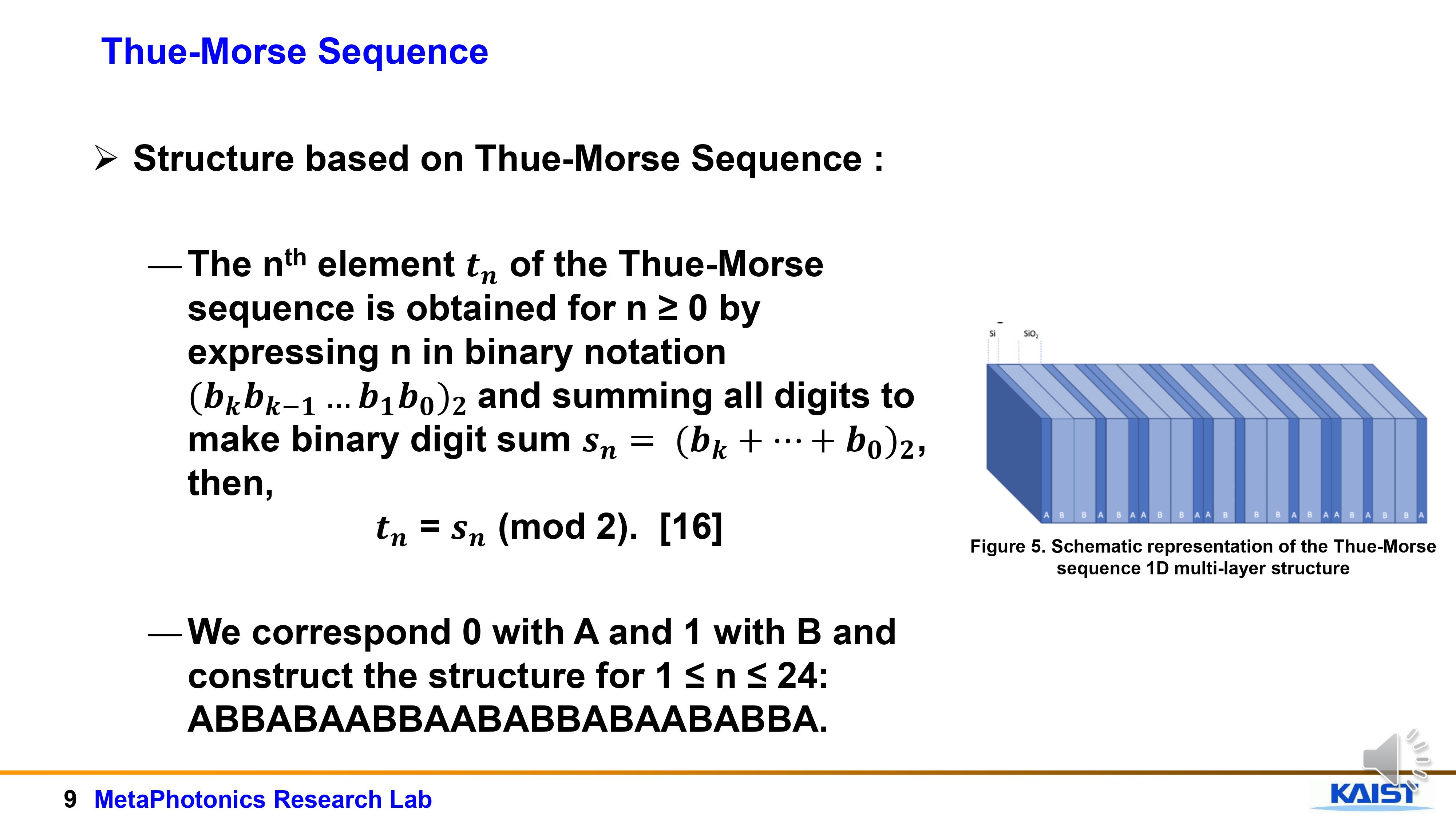 |
This is the Thue-Morse Sequence
The nth element tn of the Thue-Morse sequence is obtained for n ≥ 0 by expressing n in binary notation (bkbk-1…b1b0)2 and summing all digits to make binary digit sum Sn = (bk + … + b0), then,� tn = Sn (mod 2). []
We correspond 0 with A and 1 with B and construct the structure for 1 ≤ n ≤ 24: ABBABAABBAABABBABAABABBA.
|
| ICACT20220296 Slide.10
[Big Slide]
[YouTube] |
Chrome Click!! |
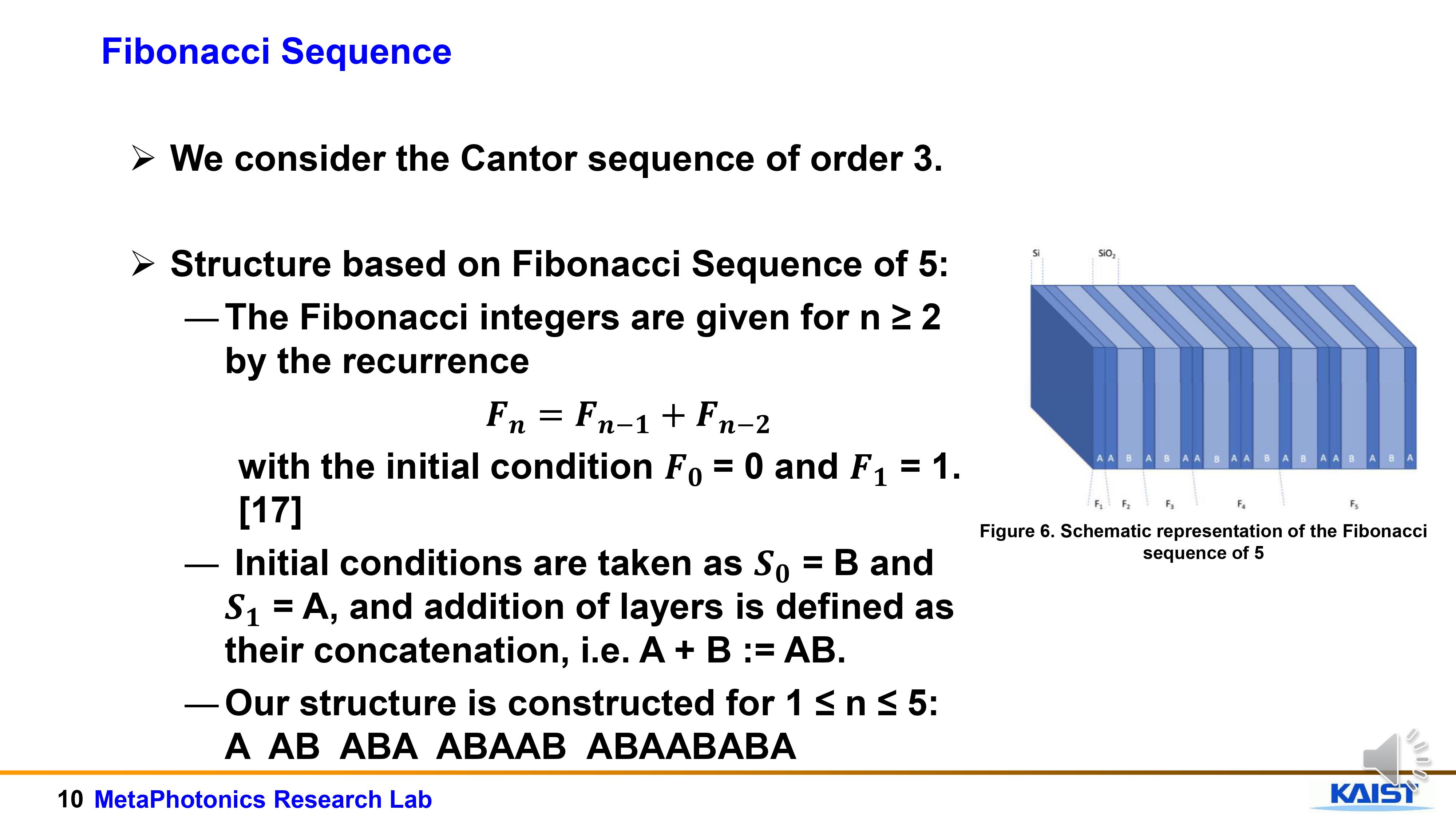 |
The Fibonacci sequence of integers is given for n ≥ 2 by the recurrence of the previous two numbers
with the initial condition F0 = 0 and F1 = 1. [ ].
In our structure take the Initial conditions as S0 = B and S1 = A, and addition of layers is defined as their concatenation, i.e. A + B := AB.
Our structure is constructed for 1 ≤ n ≤ 5: A AB ABA ABAAB ABAABABA
|
| ICACT20220296 Slide.11
[Big Slide]
[YouTube] |
Chrome Click!! |
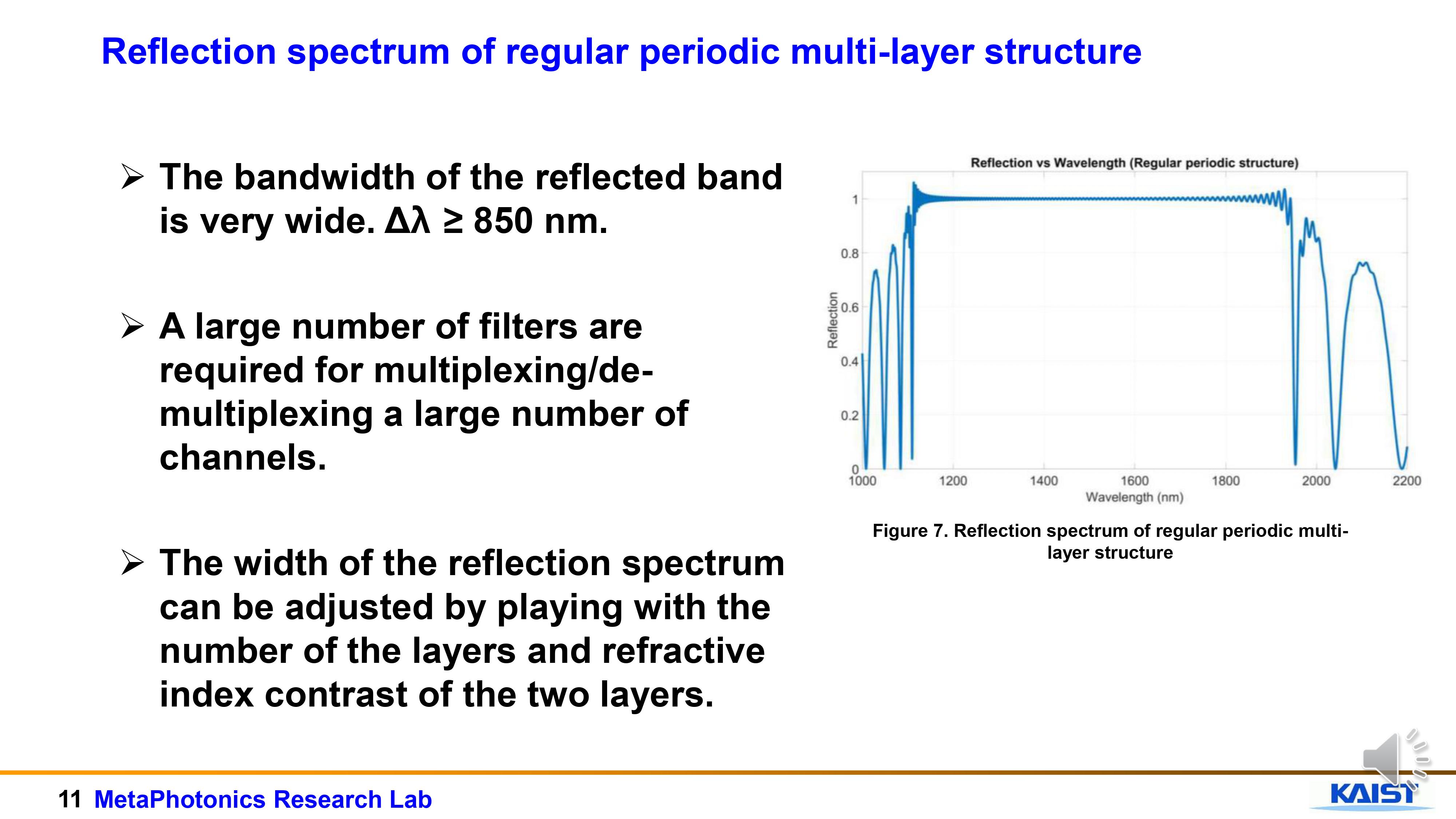 |
This is the reflected spectrum of regular periodic multi-layer structure.
We see that the bandwidth of the reflected band is very wide. That is Δλ ≥ 850 nm.
As a result, a large number of filters are required for multiplexing/de-multiplexing a large number of channels.
|
| ICACT20220296 Slide.12
[Big Slide]
[YouTube] |
Chrome Click!! |
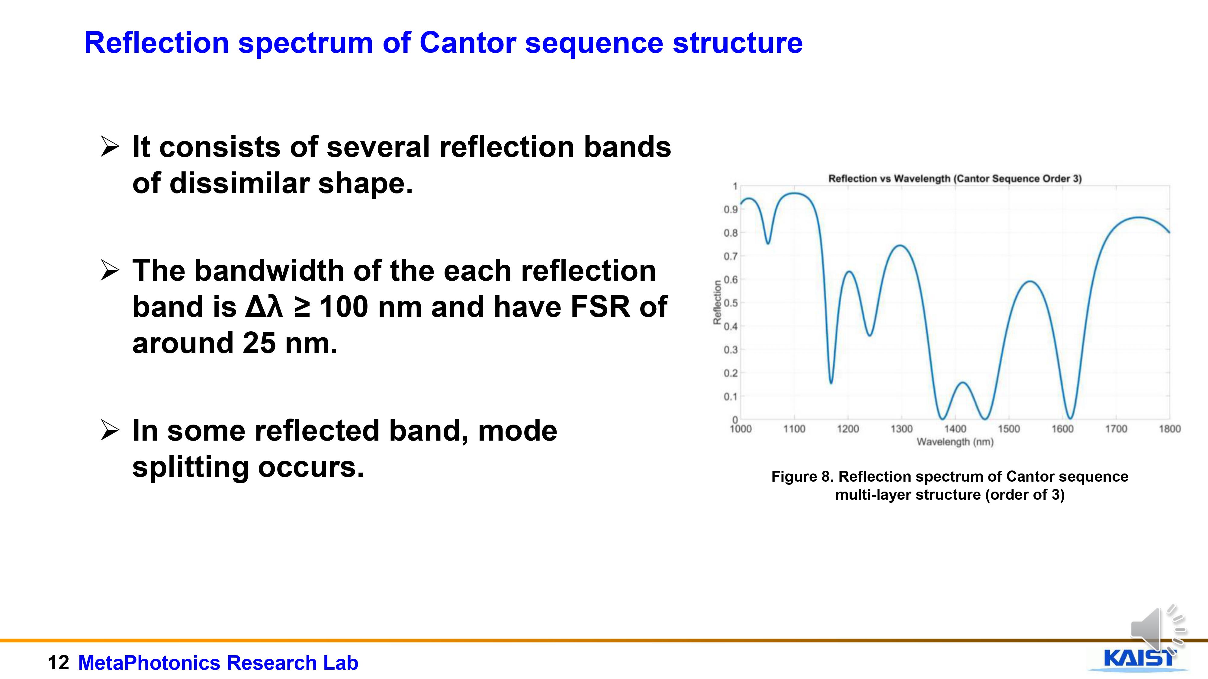 |
In the reflection spectrum of the cantor sequence, we see that it consists of several reflection bands of dissimilar shape
The bandwidth of the each reflection band is around Δλ ≥ 100 nm and have Free spectral range (FSR) of around 25 nm.
Also, we see that, in some reflected band, mode splitting occurs.
|
| ICACT20220296 Slide.13
[Big Slide]
[YouTube] |
Chrome Click!! |
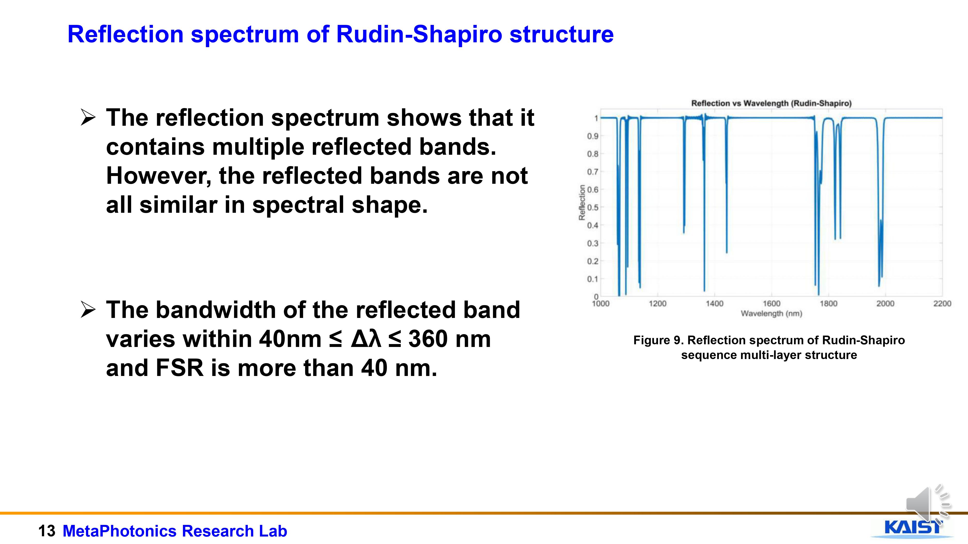 |
The reflection spectrum of Rudin-Shapiro shows that it contains multiple reflected bands. However, the reflected bands are not all similar in spectral shape.
The bandwidth of the reflected band varies within 40nm ≤ Δλ ≤ 360 nm and FSR is more than 40 nm.
|
| ICACT20220296 Slide.14
[Big Slide]
[YouTube] |
Chrome Click!! |
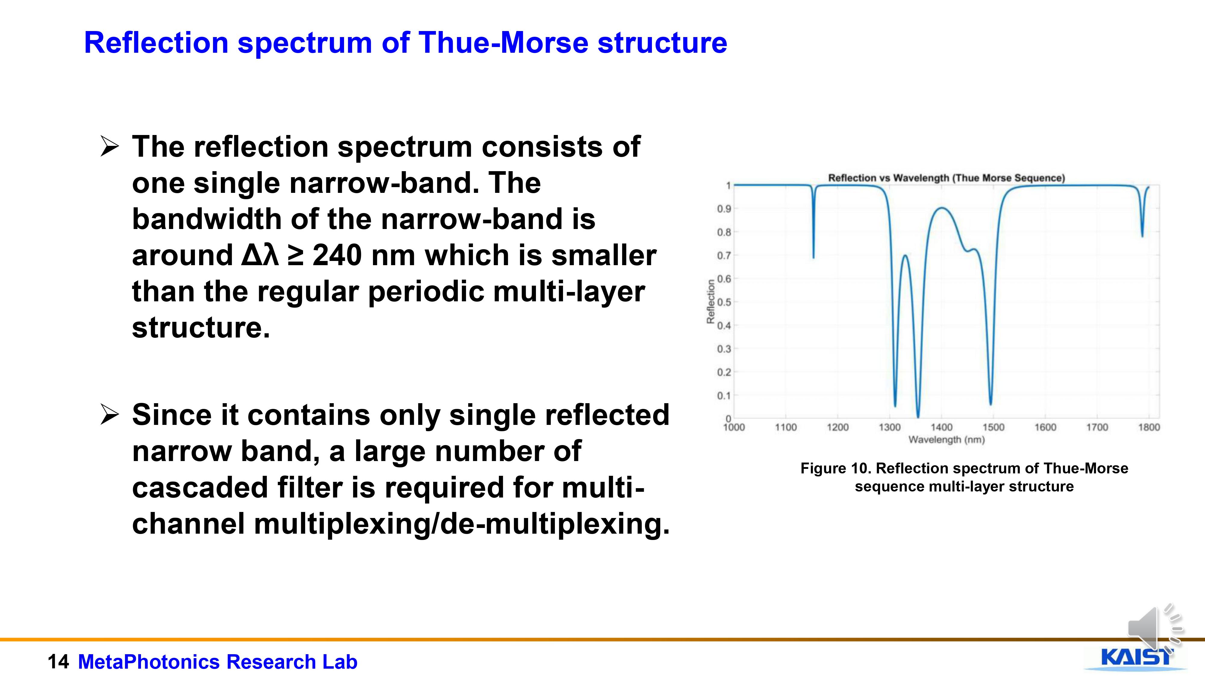 |
In case of Thue-Morse structure, the reflection spectrum consists of one single narrow-band. The bandwidth of the narrow-band is around Δλ ≥ 240 nm which is smaller than the regular periodic multi-layer structure.
Since it contains only single reflected narrow band, a large number of cascaded filter is required for multi-channel multiplexing/de-multiplexing.
|
| ICACT20220296 Slide.15
[Big Slide]
[YouTube] |
Chrome Click!! |
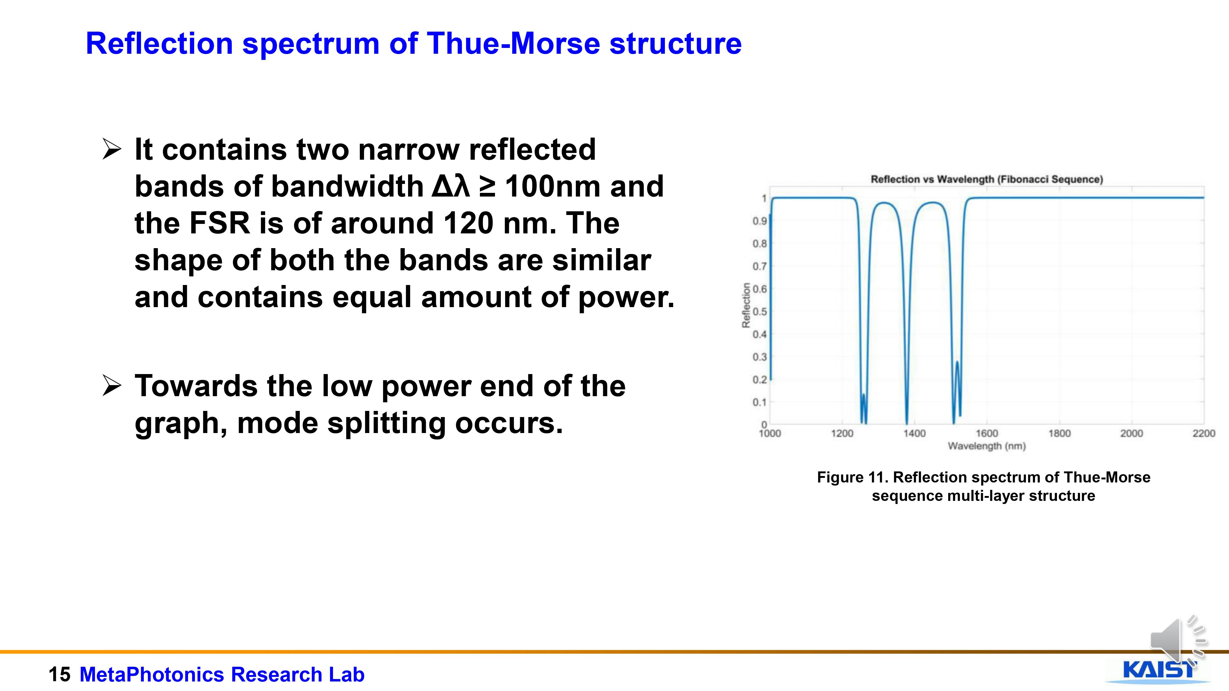 |
In Thue-morse structure, the reflection spectrum contains two narrow reflected bands of bandwidth Δλ ≥ 100nm and the FSR is of around 120 nm. The shape of both the bands are similar and contains almost equal amount of power.
Towards the low power end of the graph, mode splitting occurs.
Towards the low power end of the graph, mode splitting occurs.
|
| ICACT20220296 Slide.16
[Big Slide]
[YouTube] |
Chrome Click!! |
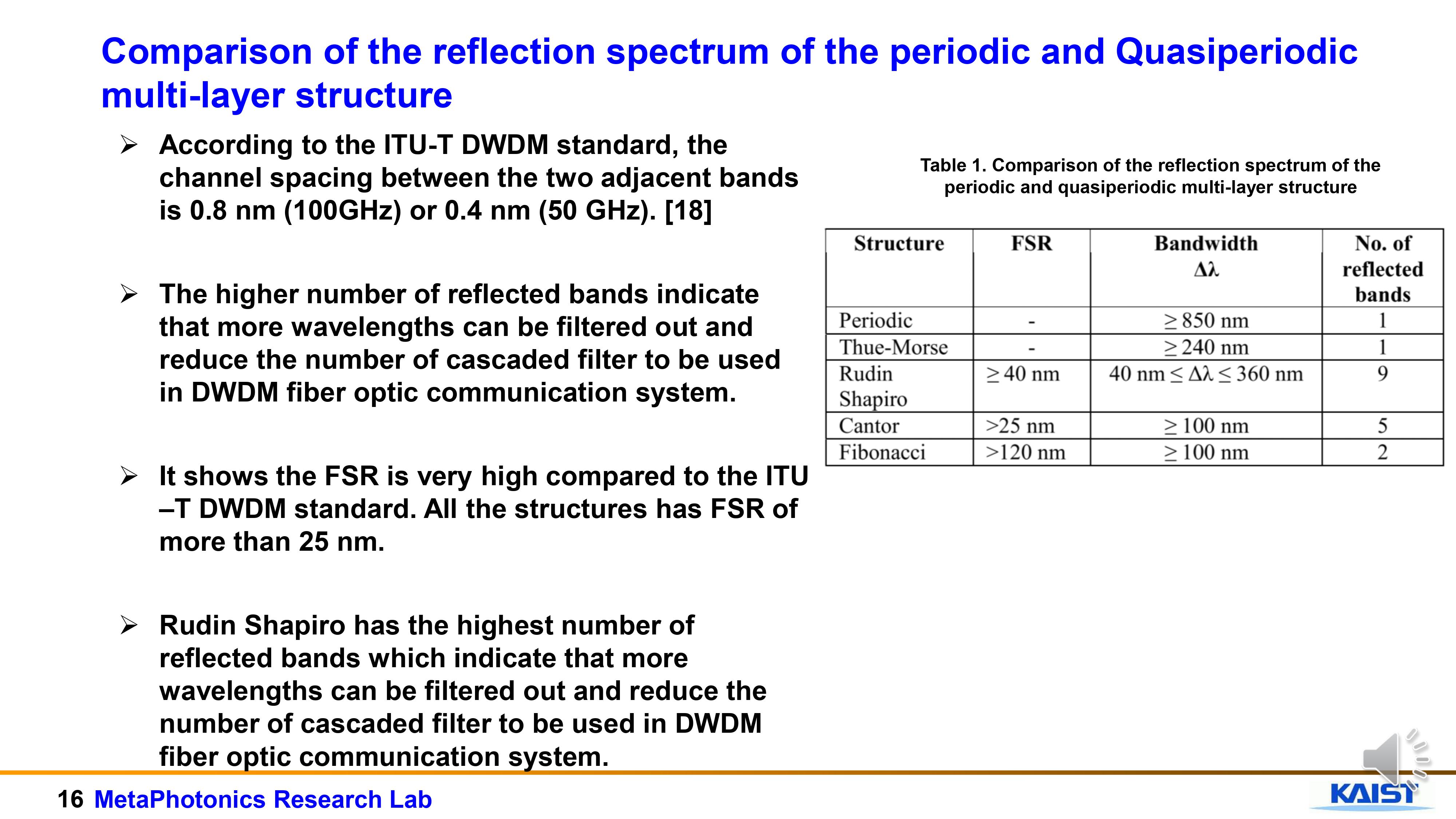 |
According to the ITU-T DWDM standard, the channel spacing between the two adjacent bands is 0.8 nm (100GHz) or 0.4 nm (50 GHz). [18]
The higher number of reflected bands indicate that more wavelengths can be filtered out and reduce the number of cascaded filter to be used in DWDM fiber optic communication system.
It shows the FSR is very high compared to the ITU –T DWDM standard. All the structures has FSR of more than 25 nm.
Rudin Shapiro has the highest number of reflected bands which indicate that more wavelengths can be filtered out and reduce the number of cascaded filter to be used in DWDM fiber optic communication system.
|
| ICACT20220296 Slide.17
[Big Slide]
[YouTube] |
Chrome Click!! |
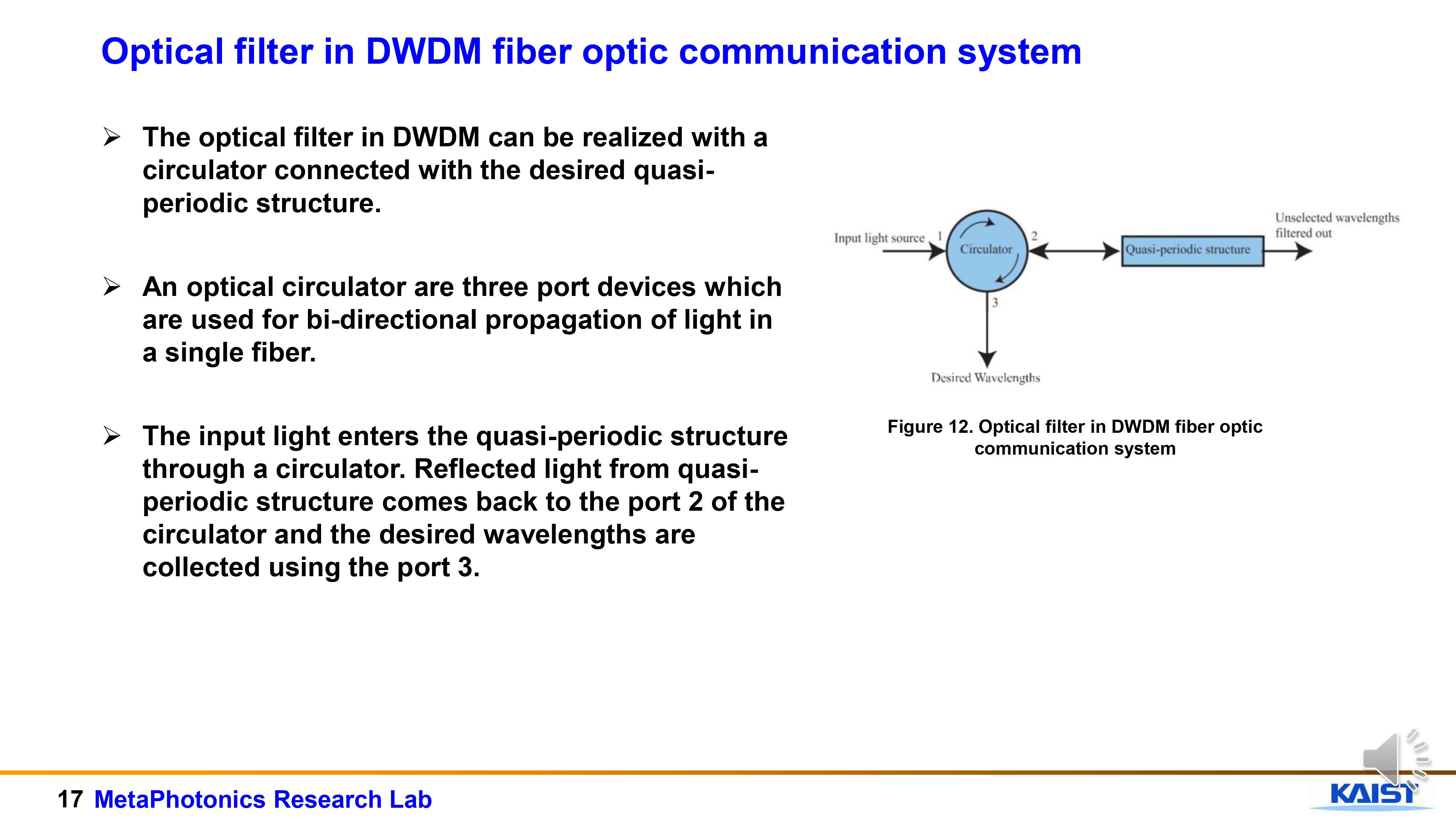 |
The optical filter in DWDM can be realized with a circulator connected with the desired quasi-periodic structure.
An optical circulator are three port devices which are used for bi-directional propagation of light in a single fiber.
The input light enters the quasi-periodic structure through a circulator. Reflected light from quasi-periodic structure comes back to the port 2 of the circulator and the desired wavelengths are collected using the port 3.
|
| ICACT20220296 Slide.18
[Big Slide]
[YouTube] |
Chrome Click!! |
 |
We discussed reflection spectra of periodic and four well-known quasiperiodic (Thue-Morse, Rudin Shapiro, Cantor, and Fibonacci) which are obtained using FDTD method.
We demonstrated the feasibility of the structures in optical filtering application by comparing it with the ITU-T DWDM standard.
Although it is difficult to achieve the compatibility with the ITU-T DWDM standard with the straight-forward design of these multi-layer structures, these comparisons will pave the way to achieving an optimized versions of these multi-layer structure in the near-future work
Future optimization approach: Inverse design using Particle Swarm Optimization (PSO) or Deep Neural Networks (DNN).
|
| ICACT20220296 Slide.19
[Big Slide]
[YouTube] |
Chrome Click!! |
 |
That's for the presentation and thank you for your attention |
| ICACT20220296 Slide.20
[Big Slide]
[YouTube] |
Chrome Click!! |
 |
The references are shown |
| ICACT20220296 Slide.21
[Big Slide]
[YouTube] |
Chrome Click!! |
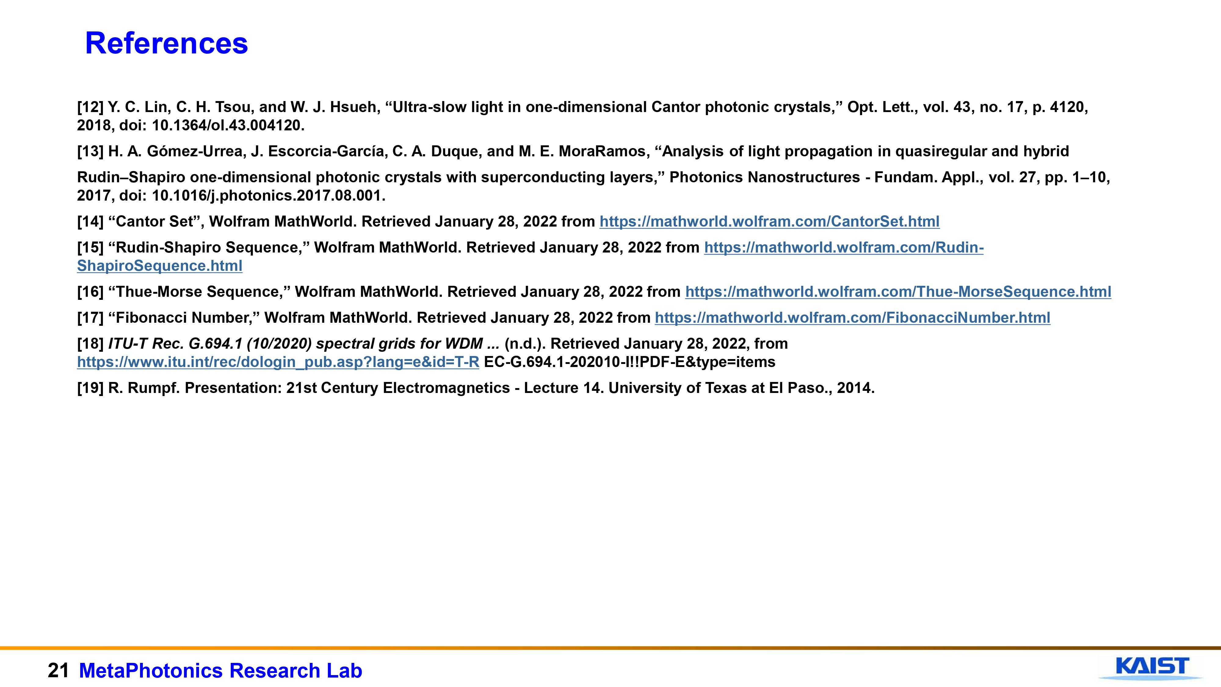 |
The references are shown |















