Now 7074 visitors
Today:0 Yesterday:0
Total: 156641
216S 51P 5R
2026-10-22, Week 43 |
| Member Login |
| TACT Journal Homepage |
| Call for Paper |
| Committee |
| Find My Paper |
| Author Homepage |
| Statistics & History |
| Welcome Message |
| Paper Procedure |
| FAQ |
| Paper Archives |
| Outstanding Papers |
| Author Homepage |
| - Paper Procedure |
| - Journal Procedure |
| - Presentation Tips |
|
| Program & Proceedings |
| Program with Papers |
| Plenary Session |
| Tutorial Session |
|
| Presentation Platform |
| Hotel & Travel Info |
| About Korea |
| Accommodation |
| Transportation |
| VISA |
| Other Infomation |
|
| Photo Gallery |
| Scheduler Login |
| Seminar |
| Archives Login |
|
| Sponsors |

|

|

|

|

|

|

|

|

|

|
|
|
|
|
 ICACT20230159 Slide.00
[Big Slide]
[YouTube] |
Chrome  Click!! |
 |
hello my name is joowon from university of sejong. now i talking about DC nanogrid which is using IEC 61850 |
| ICACT20230159 Slide.01
[Big Slide]
|
Chrome Click!! |
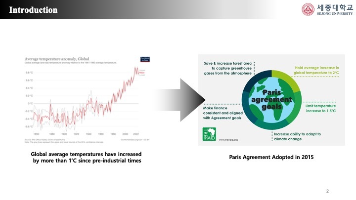 |
While the world is facing a climate crisis due to global warming, efforts are being made to solve environmental destruction through technological development.
According to the graph on the left, it can be seen that the red line, which represents the annual average temperature trend over time, has risen steeply since the Industrial Revolution.
This means that artificial greenhouse gas emissions have caused an average temperature increase of 1.1 degrees worldwide.
Gray lines represent upper and lower confidence intervals.
As a result, as the need to reduce greenhouse gases emerged, the Paris Climate Agreement which is the first climate agreement was signed in 2016, and carbon neutrality was declared in some countries to reduce greenhouse gases.
|
| ICACT20230159 Slide.02
[Big Slide]
|
Chrome Click!! |
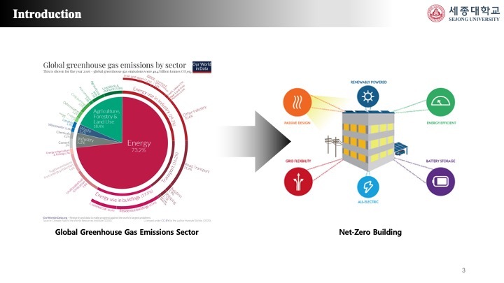 |
Energy generation and consumption, which are the main causes of greenhouse gas emissions, accounted for the majority of greenhouse gas emissions, accounting for about 73.2% as of 2021.
The World Green Building Council reported that about 40% of it is emitted by energy used in buildings, and greenhouse gas emissions from buildings are now even higher.
To solve this problem, efforts are being made to create NetZero buildings that can reduce greenhouse gases in large quantities by producing eco-friendly energy and supplying energy to buildings.
|
| ICACT20230159 Slide.03
[Big Slide]
|
Chrome Click!! |
 |
Currently, centralized power generation centered on large-scale fossil fuel power generation facilities is the main focus.
About 30.8 billion tons of carbon dioxide are released into the atmosphere every year, and it has been decreasing for about two years and then increasing again.
Centralized power generation mainly uses a one-way AC power grid that facilitates voltage boosting and lowering.
However, the one-way AC power grid has a problem of surplus power processing, an increase in power conversion equipment due to an increase in DC load, and an energy loss due to long-distance transmission, which degrades energy efficiency, so a new power grid is required to solve this problem.
Therefore, it is necessary to switch to a distributed power generation system centered on small-scale power generation facilities that can actively accommodate renewable energy
|
| ICACT20230159 Slide.04
[Big Slide]
|
Chrome Click!! |
 |
Distributed power generation systems centered on small power generation facilities are seen as solutions to increase energy efficiency as they can actively accommodate renewable energy.
As the demand for distributed power generation systems and energy storage systems (ESSs) increases in island and mountainous areas, research on small-scale power grids is being actively conducted.
In general, smart grids and microgrids that use multiple renewables as small independent power grids are used as solutions.
However, since microgrids cannot replace conventional power grids due to the difficulty of maintaining power quality, DC nanogrid, which can bundle power and communication between small power grids, has recently emerged as a solution to increase energy efficiency.
|
| ICACT20230159 Slide.05
[Big Slide]
|
Chrome Click!! |
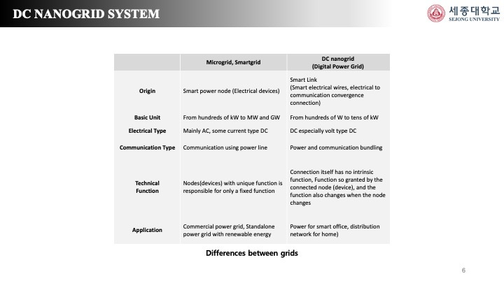 |
DC Nanogrid is a low-voltage, low-power digital power grid with the potential of existing power systems in the future and is a kW-level small distributed autonomous grid module that can bundle power and communication.
DC nanogrid is a smart version of a link, which differs in its approach from existing smart grids or microgrids that deal with nodes.
The following Table 1 shows the differences between the existing smart grids, microgrids, and nanogrid.
According to the following table, unlike microgrids and smart grids that use smart power nodes, nanogrid uses smart links, which are telecommunication convergence connections.
Among them, simple modularity, which is the core of DC nanogrid, is a power grid that can be modularized to develop at a lower cost than microgrid.
Because of simple modularity, it can reduce the installation cost and maintenance cost burden of consumers.
|
| ICACT20230159 Slide.06
[Big Slide]
|
Chrome Click!! |
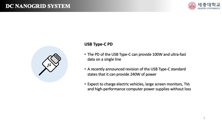 |
This paper proposes a test bed environment for DC nanogrid system for buildings that can provide USB Type-C PD-based power and high-speed data for interoperability.
The PD of USB Type-C can provide 100W and high-speed data in a single line according to the standards defined in USB-IF.
The latest revision of the USB Type-C standard, recently announced by USB-IF, shows that 240W of power can be supplied, which will enable future electric vehicle charging, large-screen monitors, or power supplies for TVs and high-performance computers without loss.
In addition, the EU has agreed to unify the charging terminals of all new portable devices in Europe to USB Type-C by autumn 2025, regardless of manufacturer.
DC Nanogrid, which uses USB Type-C PD, is expected to increase demand in the future, can provide various power devices through one PD gateway to provide power grid and data communication services as a single channel, which can control load data in more detail than the existing power grid.
|
| ICACT20230159 Slide.07
[Big Slide]
|
Chrome Click!! |
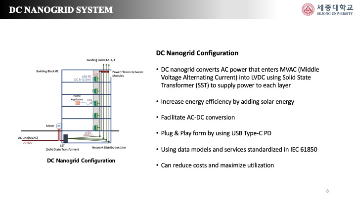 |
As shown in the figure on the left, the dc nanogrid proposed in this paper converts the ac power supplied to the middle voltage into low voltage dc power using SST.
Each layer receives LVDC through usb-c type, and communicates power consumption and necessary data. At this time, solar energy was added to increase energy efficiency.
The added solar power energy is used as the main energy source, and AC power is used when solar power is insufficient.
Therefore, relays were installed at each layer to facilitate ac-dc conversion and efficient energy management.
By providing power supply information in the building to each node accurately and quickly, micro-optimal operation is possible, so that the existing ac infrastructure can be replaced with dc technology and converted to plug & play that can provide power and communication together using usb type-cpd.
In addition, data models and services standardized in IEC 61850 will be used to collect nanogrid in the future to form microgrids and microgrids to enable commercial power distribution network configuration, enabling more efficient energy management systems.
With technology applicable regardless of the environment, it can realize universal power services that significantly reduce costs and maximize utilization.
|
| ICACT20230159 Slide.08
[Big Slide]
|
Chrome Click!! |
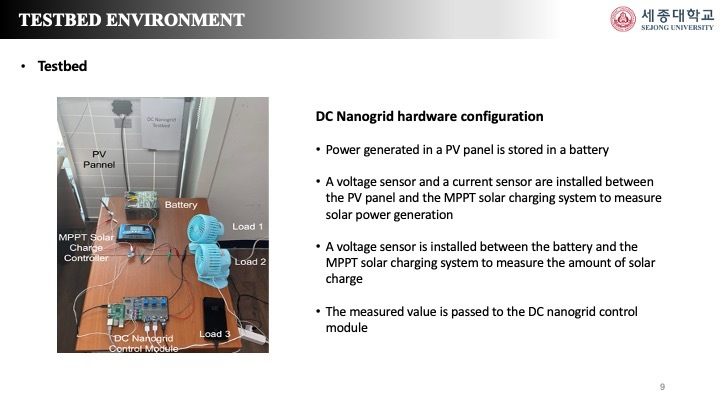 |
The figure on the next left is the configuration of the testbed of the previous dc nanogrid.
The test bad hardware consists of PV pannel, Battery, MPPT Control Module, DC Load, AC Barrel Jack, Voltage Sensor, Ampere Sensor, MCP3008 and Relay.
Power generated from the Pv panel is stored in the battery.
At this time, a voltage sensor and a current sensor were installed between the pv panel and the mppt to measure the amount of power generated, and the sensor was installed between the battery and the mppt in the same manner as above to measure the battery storage.
The amount of power may be calculated using the value measured by the sensor, and the calculated amount of power may be transmitted to the control module of the DC nanogrid.
|
| ICACT20230159 Slide.09
[Big Slide]
|
Chrome Click!! |
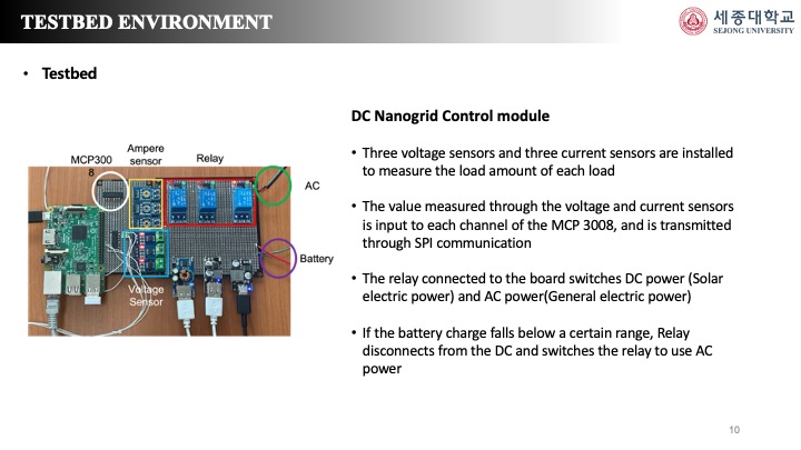 |
The left figure is the configuration of the control module of the aforementioned dc nanogrid.
Three voltage sensors and three current sensors were installed to measure the power consumed by each load.
The value measured by the installed sensor enters the input of the mcp8003 module and is converted into digital data for SPI communication of Raspberry Pi in mcp3008, an analog to digital converter.
The relay on the upper right is installed to switch ac power and dc power generated from the solar panel, and when the storage amount of the battery falls below a certain amount, the relay is connected to ac power to disconnect from the battery that is dc power and receive ac power.
|
| ICACT20230159 Slide.10
[Big Slide]
|
Chrome Click!! |
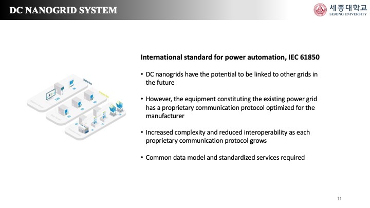 |
The communication between Raspberry Pi and the client, which is the server in the previous structure, was implemented in accordance with IEC 61850, an international standard.
IEC 61850 is an international standard for power automation that ensures interoperability in the field of power.
Equipment constituting the existing power grid cannot communicate freely with other companies using protocols optimized for manufacturers.
Therefore, the IEC 61850 standard was produced to reduce the inability to operate efficient power grids due to increased complexity and reduced interoperability by different protocols.
Since the dc grid proposed in this paper can also be used in connection with other grids in the future, the logical nodes defined in IEC61850-7-4 were used according to the standard for interoperability.
|
| ICACT20230159 Slide.11
[Big Slide]
|
Chrome Click!! |
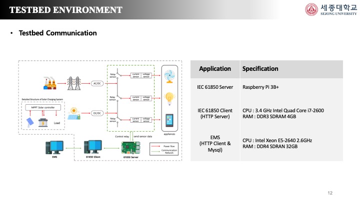 |
The diagram on the next left is a diagram of the communication structure of the test bad.
It was implemented using mmslite api, an api according to IEC 61850.
Raspberry Pi, an IEC 61850 server, measures solar power generation, battery storage, and power consumed by the load and maps it to the corresponding logical node.
IEC 61850 client requests the measured value to the server, which uses mms to send the requested value to the client.
The Client acts as a server supporting HTTP communication at the same time and transmits the measured value to the EMS.
The EMS posts the received value on the web page, and relay control is also possible on the web page.
|
| ICACT20230159 Slide.12
[Big Slide]
|
Chrome Click!! |
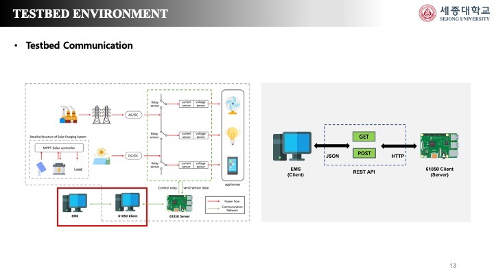 |
In the figure on the right, IEC 61850 server and EMS use http communication.
The HTTP communication structure was constructed by implementing the RESTful API Server for communication of measured values in the 61850 Client using the Spring boot framework, and implementing the RESTful API Client in the EMS located in the external server room.
Mysql DB was used as a database to store the received data.
To collect data measurements for dynamic power monitoring, the Client sends a POST request message to the EMS, receives the message from the EMS, and stores the measured value in the Mysql DB.
After analyzing the data collected by the server, the client can send a GET request message to the server to obtain an appropriate status value for the relay, receive a response message, and then control the relay.
|
| ICACT20230159 Slide.13
[Big Slide]
|
Chrome Click!! |
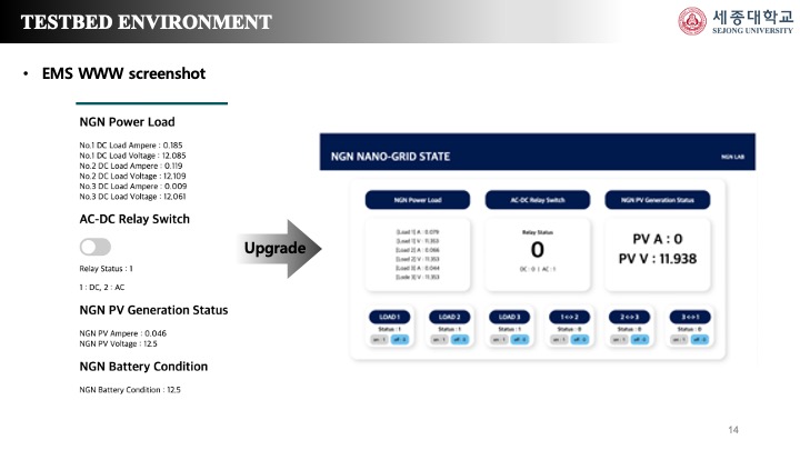 |
The screen is the EMS system web screen of the test bad using IEC 61850 standard, the left side is a photo attached to the paper, and has now been upgraded to the right side screen.
The web shows the current and voltage measurements of three DC loads from No. 1 to No. 3.
The AC-DC Relay indicates what power is currently used, and the AC-DC can be switched by controlling the relay through the button.
In addition, the voltage and current measurements of power generation can be checked in the PV Pannel, and the Battery Condition can be seen.
The EMS system can centrally control the power of the entire building in the future, and it is expected that automatic AC-DC conversion can solve the power quality problem of the existing microgrid by system-connected, enabling efficient energy management.
In addition, surplus power generated from the photovoltaic energy of DC nanogrid can be easily traded in the power brokerage market.
|
| ICACT20230159 Slide.14
[Big Slide]
|
Chrome Click!! |
 |
thanks. |
| |





